Liquid-crystal displaying device and producing method thereof

A technology of liquid crystal display and manufacturing method, applied in instruments, nonlinear optics, optics and other directions, can solve the problems of damage to the multilayer film structure, time-consuming and labor-intensive, etc., so as to shorten the time course of the operation, reduce the cost, and avoid errors. effect of possibility

Active Publication Date: 2007-10-10
AU OPTRONICS CORP
View PDF8 Cites 0 Cited by
  • Summary
  • Abstract
  • Description
  • Claims
  • Application Information

AI Technical Summary

Problems solved by technology

If the black tape is not attached smoothly, there is a possibility of light leakage, and the black tape 22 must be torn off and then redo the lamination process. First, it is time-consuming and labor-intensive. Second, repeated tearing and pasting of the black tape 22 will cause polarizers 18 multilayer film structure damage

Method used


Image

  • Liquid-crystal displaying device and producing method thereof
  • Liquid-crystal displaying device and producing method thereof
  • Liquid-crystal displaying device and producing method thereof

Examples


Embodiment Construction

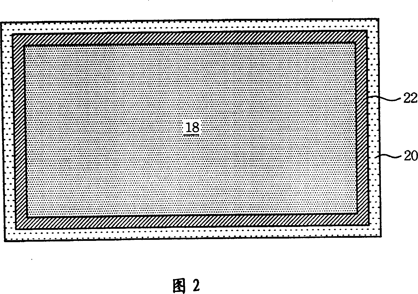
[0034] As shown in FIG. 6, the liquid crystal display of the present invention forms a light-shielding material 60 in a specific area around the lower and upper polarizers 28, 30, so that only the lower and upper polarizers 29, 30 need to be bonded to the liquid crystal panel during the assembly operation. 23, the effect of preventing light leakage can be achieved, and thereby the utilization rate of the light source of the present invention can be improved.

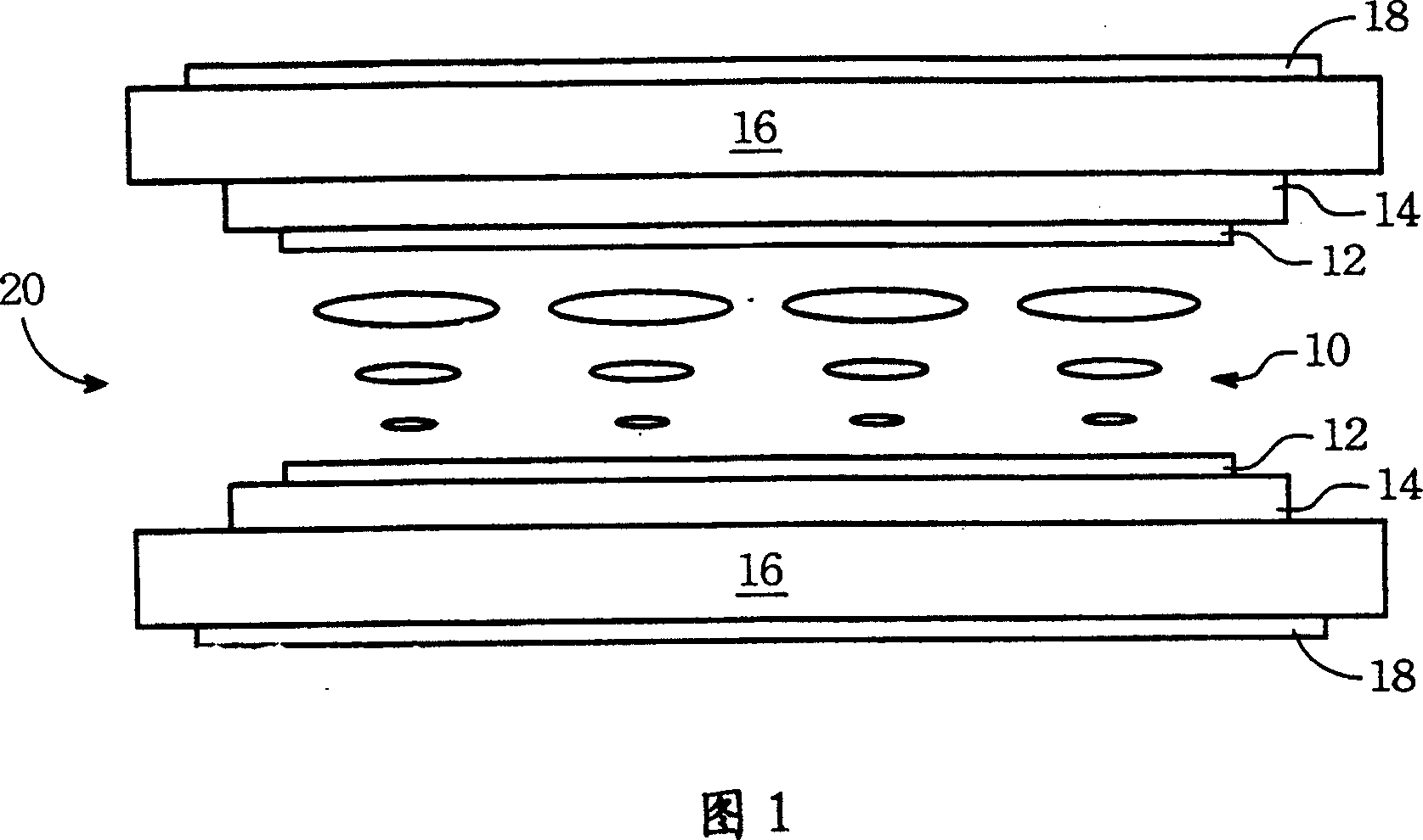
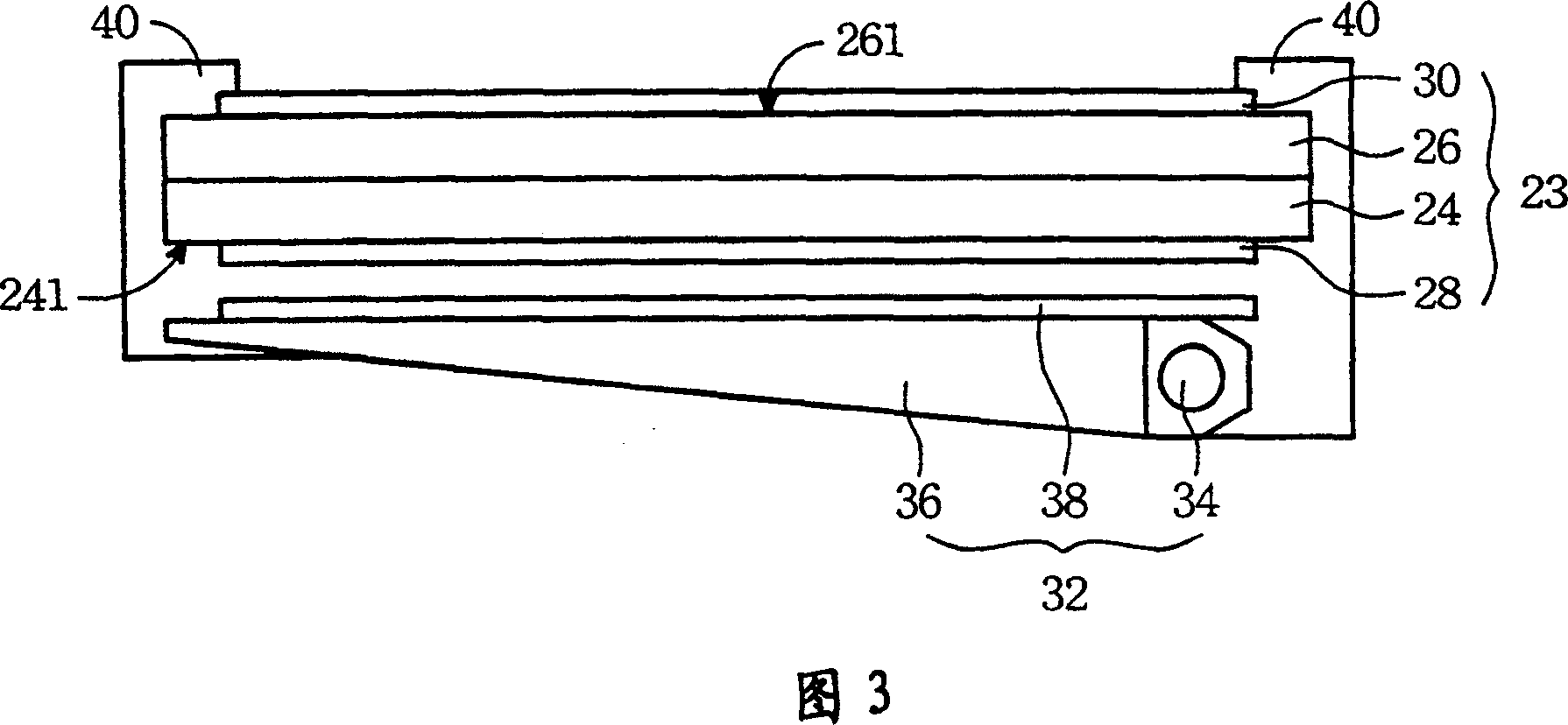
[0035] As shown in FIG. 3 , the liquid crystal display of the present invention includes a liquid crystal panel 23 , a lower polarizer 28 , an upper polarizer 30 , a backlight module 32 and an outer frame 40 located below the liquid crystal panel 23 as the light source of the liquid crystal display of the present invention.

[0036] As shown in FIG. 4 , the liquid crystal panel 23 includes a lower transparent substrate 24 , an upper transparent substrate 26 and a liquid crystal layer 25 .

[0037] The lower surface of th...


PUM


Abstract

A liquid crystal display comprises liquid crystal panel, top and bottom polarized light plated and back light module, liquid crystal panel consists of light incoming and outgoing face with liquid crystal layer set in between the two faces, shading material is formed on peripheral edge of top and bottom polarized light plate by coating / spraying / screening or reprining, top and bottom polarized light plates are set separately on light incoming and outgoing faces. The preparing method includes the provide light incoming and outgoing faces, liquid crystal panel, top and bottom polarized light plates, shading material, back light module ad outer-frame.

Description

technical field [0001] The invention belongs to a method for manufacturing a display device, in particular to a method for manufacturing a liquid crystal display. Background technique [0002] Since the invention of the first black-and-white TV with a cathode ray tube as the working mode in 1972, display technology has been evolving at a rapid pace. However, such a display working in the cathode ray tube mode has disadvantages such as large volume, heavy weight, and high radiation dose. Therefore, various flat display technologies have been continuously developed, such as liquid crystal displays, field emission displays, and plasma televisions. [0003] Among these flat panel display technologies, liquid crystal displays are the most sophisticated and popular products. Liquid crystal displays have the advantages of light weight, power saving, portability, no radiation, and full color. For example, common mobile phones, language translators, digital cameras and video camera...

Claims


Application Information

Patent Timeline
IPC IPC(8): G02F1/1335G02F1/1333G02F1/13357
Inventor 杨金城吴俊翰
Owner AU OPTRONICS CORP
Why Eureka
Try Eureka