Apparatus and method for controlling ring laser optical cavity length

A ring laser and optical cavity technology, applied in the laser field, can solve problems such as high power consumption, affecting the performance of ring lasers, laser gyro measurement accuracy, and affecting applications

Inactive Publication Date: 2007-11-14
XIDIAN UNIV
View PDF0 Cites 0 Cited by
  • Summary
  • Abstract
  • Description
  • Claims
  • Application Information

AI Technical Summary

Problems solved by technology

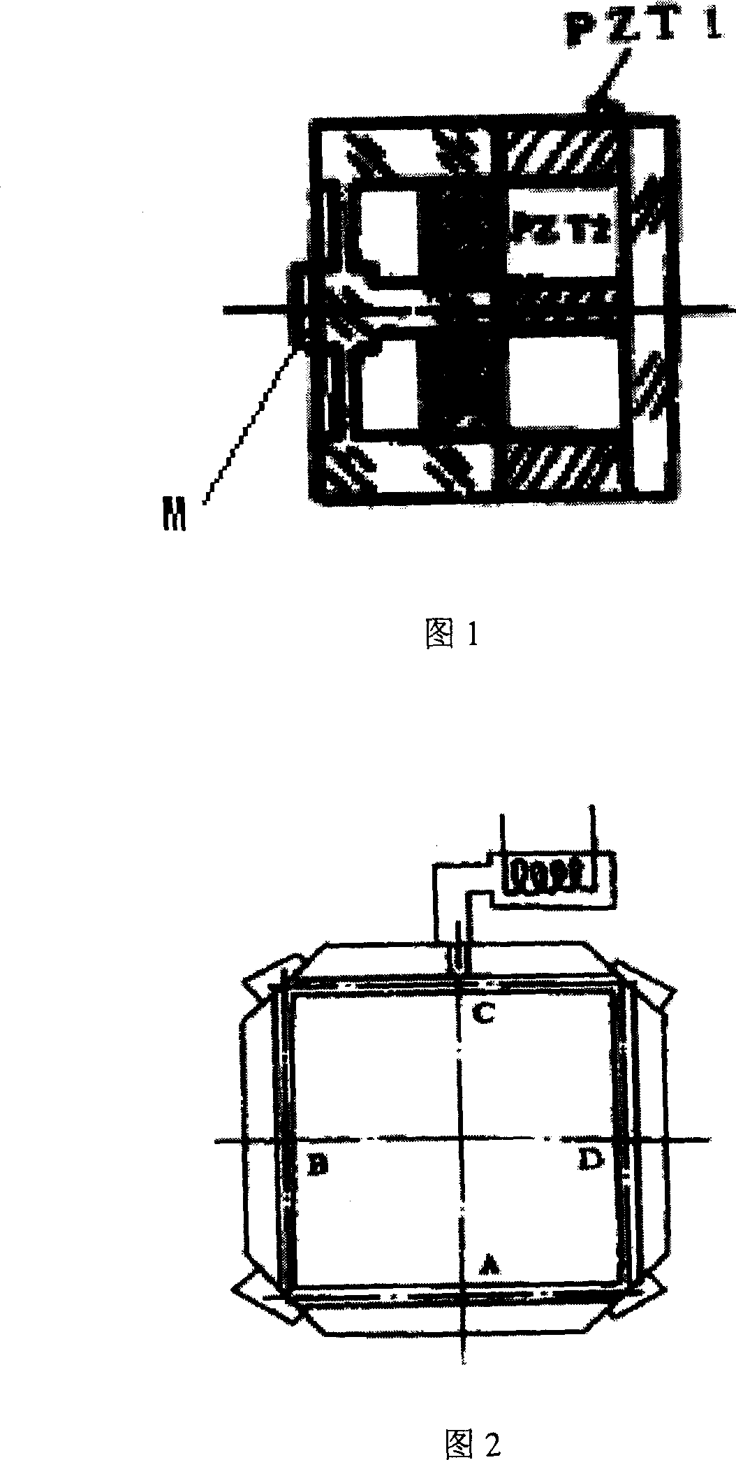
[0015] Chinese Journal of Inertial Technology, 1994, 2(4): 50-57, the article "Frequency Stabilization System of Laser Gyro LG" published by Ma Younian and Yuan Xiaodong and related materials pointed out that the first control ring laser optical cavity length The device is mainly used in the frequency stabilization system of the mirror ring laser. It has the advantages of simple structure, high sensitivity and fast response speed. However, due to the bending deformation of the piezoelectric element during its stretching process, it will seriously affect the ring laser. The performance of the laser and the measurement accuracy of the laser gyroscope; the second device for controlling the length of the optical cavity of the ring laser is mainly used in the frequency stabilization system of the total reflection prism ring laser, and it does not change during the control of the length of the optical cavity. The optical path of the ring laser has a simple control method, which can solve the problem that the total reflection prism ring laser is difficult to control the geometric length of the resonator, but there are the following shortcomings, which affect its application in high-precision laser gyroscopes:
[0016] (1) There is a temperature gradient between the device controlling the length of the optical cavity and the laser, which seriously affects the performance of the ring laser and the measurement accuracy of the laser gyroscope;
[0017] (2) The adjustment time of the optical cavity length control device is long, and the starting speed and response speed are low;
[0018] (3) High power consumption

Method used


Image

  • Apparatus and method for controlling ring laser optical cavity length
  • Apparatus and method for controlling ring laser optical cavity length
  • Apparatus and method for controlling ring laser optical cavity length

Examples


Embodiment 1

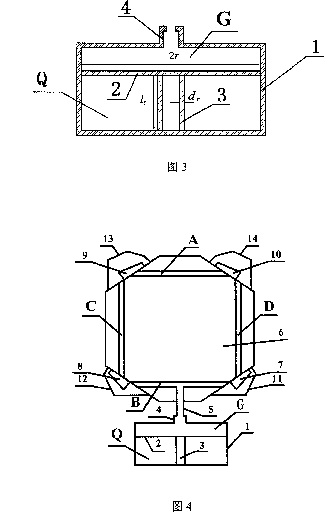
[0071] The device for controlling the optical cavity length of the ring laser proposed by the present invention can be used in the frequency stabilization system of the total reflection prism ring laser, as shown in FIG. 4 . The nozzle 4 in the device for controlling the optical cavity length of the ring laser is connected to the capillary B in the total reflection prism ring laser through the heat insulating tube 5, 6 is the cavity of the ring laser, 7-10 are the total reflection prisms, 11-14 are The protective cover, A, B, C, D are the four capillaries of the ring laser. The capillary A of the ring laser is closed by total reflection prisms 9 and 10, and the gain gas is filled in the tube. The capillary B of the ring laser is closed by the protective cover 11 and 12, and the capillary B and the space G of the ring laser are filled with 1 standard Dry air at atmospheric pressure, vacuum in the capillaries C, D and space Q of the ring laser.

[0072] The device for contr...

Embodiment 2

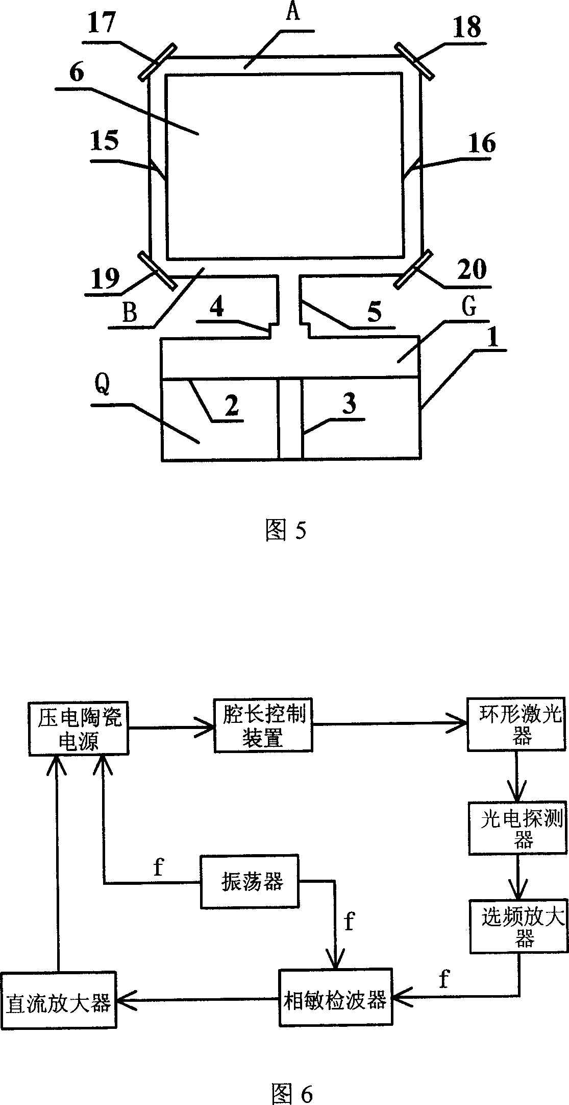
[0077] The device for controlling the optical cavity length of a ring laser of the present invention is used in a frequency stabilization system of a mirror ring laser, as shown in FIG. 5 . The nozzle 4 in the device for controlling the optical cavity length of the ring laser is connected with the capillary B in the mirror ring laser through the heat insulating tube 5 . 6 is the cavity of the mirror-type ring laser, 15 and 16 are Brewster windows, and 17-20 are mirrors. The Brewster windows 15 and 16 separate the capillary of the ring laser into two parts, A and B, and at the same time, the Brewster windows 15 and 16 seal the capillary B of the ring laser. Capillary A of the ring laser is filled with gain medium gas, capillary B and space G of the ring laser are filled with dry air at 1 standard atmospheric pressure, and space Q is vacuum. The schematic diagram of the frequency stabilization system in this embodiment is also shown in FIG. 6 .

[0078] When the ring laser ...


PUM


Abstract

The present invention discloses device and method of controlling optical cavity length of annular laser. The device consists of mainly a heat insulated container, a heat insulted elastic diaphragm and a piezoelectric ceramic chip. The heat insulted elastic diaphragm is fixed onto the heat insulated container, and the piezoelectric ceramic chip has its two ends connected separately with the heat insulted elastic diaphragm and the heat insulated container. The method includes connected the device with annular laser, filling the capillary of the annular laser with dry air, altering the voltage applied onto the piezoelectric ceramic chip to change the refractive index of dry air, to change the compensation amount of the optical cavity length of annular laser for being near to the variance in the optical cavity length of annular laser caused by outer environment change, and to realize the control on the optical cavity length of annular laser. The present invention has the advantages of fast response, high sensitivity, low power consumption, etc.

Description

technical field [0001] The invention relates to the field of laser technology, in particular to a method for controlling the optical cavity length of a ring laser by utilizing the refractive index of the dry air in the capillary of a piezoelectric ceramic electronically controlled ring laser, and is mainly used in mirror-type ring lasers, total reflection In the frequency stabilization system of prism ring laser, it can also be applied in the frequency stabilization system of straight cavity laser. Background technique [0002] Inertial technology is a general term for technologies such as inertial sensors, inertial stabilization, inertial navigation, inertial guidance and inertial measurement. It is a high-tech involving multiple disciplines. The gyroscope is a key component of inertial technology, which can sense the angular motion of a single-axis object relative to inertial space. There are many types of gyroscopes, mainly liquid floating gyroscopes, flexible gyroscopes...

Claims


Application Information

Patent Timeline
Patent Type & Authority Patents(China)
IPC IPC(8): H01S3/083
Inventor 石顺祥赵东洋李家立孙艳玲刘继芳
Owner XIDIAN UNIV
Why Eureka
Try Eureka