No-follow curren metal ceramic gas discharge tube

A gas discharge tube and metal ceramic technology, which is applied in the field of discharge tubes, can solve the problems of inability to increase the current capacity, fire, and breakage, and achieve the effect of solving the explosion of metallized ceramic tubes.

Inactive Publication Date: 2007-12-05
GUANGZHOU HOPEWELL TECH
View PDF2 Cites 1 Cited by
  • Summary
  • Abstract
  • Description
  • Claims
  • Application Information

AI Technical Summary

Problems solved by technology

[0003] According to incomplete statistics, the metal-ceramic gas discharge tubes currently used around the world have a common defect: in the lightning protection of the strong power supply system, the power supply system can provide the power supply system to maintain the discharge after the lightning overvoltage of the metal-ceramic gas discharge tube Voltage and current, so that it cannot be closed by itself after the overvoltage (that is, freewheeling)
[0016] However, this structure has the following disadvantages: First, the current capacity cannot be enlarged
Because the gas discharge gap 03 of this structure is perpendicular to the axis of the metallized ceramic tube 02, the arc is directly formed in the middle of the inner wall of the metallized ceramic tube 02 during lightning discharge. Since the arc temperature is as high as several thousand to tens of thousands of degrees, the metallized ceramic produces a huge At the same time, due to the effect of the arc temperature, the gas in the cermet gas discharge tube expands rapidly, the internal pressure rises rapidly, and the metallized ceramic tube 02 bursts under the small flow capacity, which makes the cermet gas discharge tube invalid; secondly, the The structure cannot extinguish the arc after the lightning overvoltage in the strong power supply system, and will continue to discharge until the cermet gas discharge tube fails or damages the power line due to overcurrent; finally, due to the structure of the metallized ceramic tube 02 end face The metal electrode is airtight and sealed to withstand the gas expansion force generated by the arc temperature inside the metal-ceramic gas discharge tube. It is easy to break the connection between the metallized ceramic tube 02 and the electrode 01 and make it invalid.

Method used


Image

  • No-follow curren metal ceramic gas discharge tube
  • No-follow curren metal ceramic gas discharge tube
  • No-follow curren metal ceramic gas discharge tube

Examples


Embodiment Construction

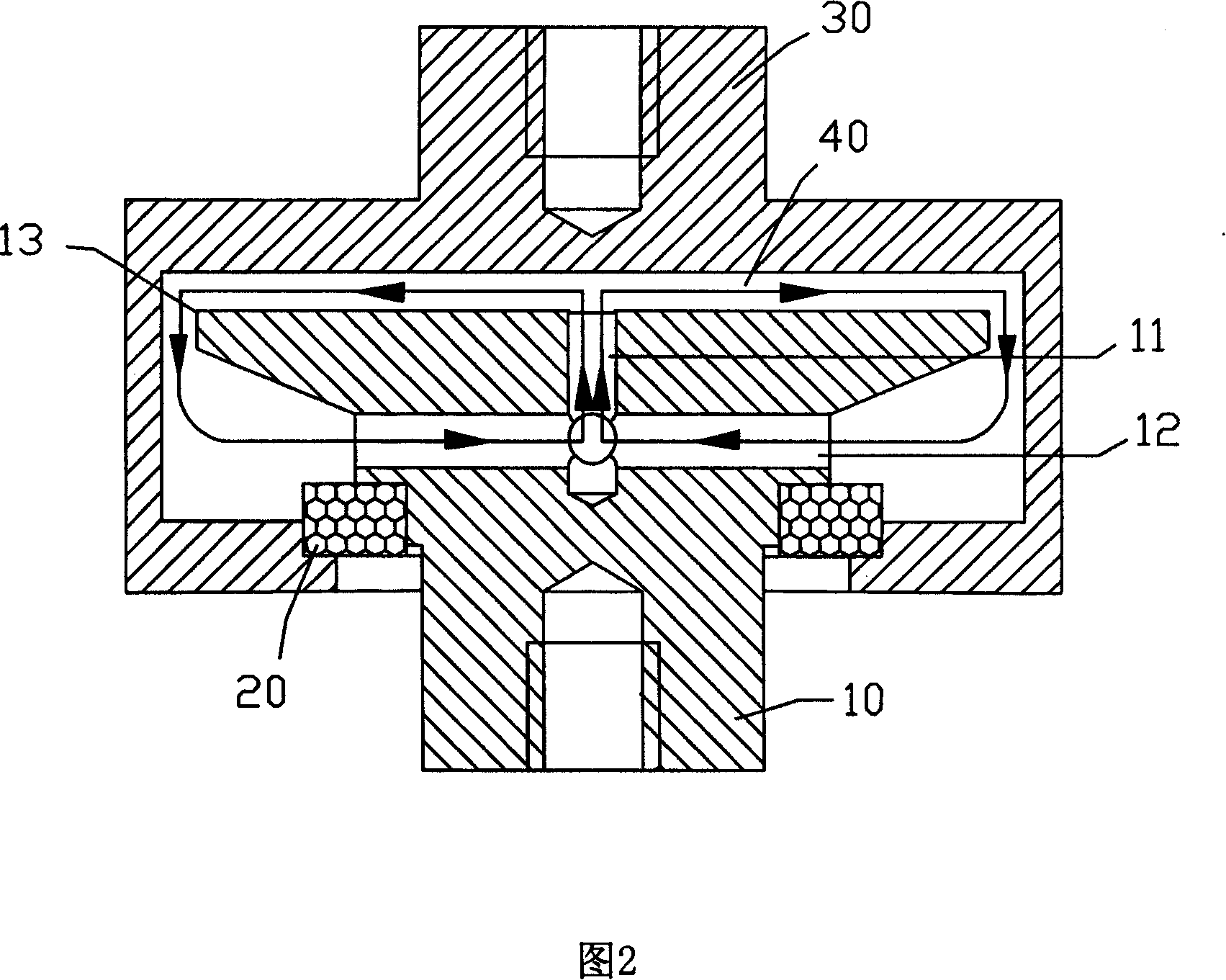
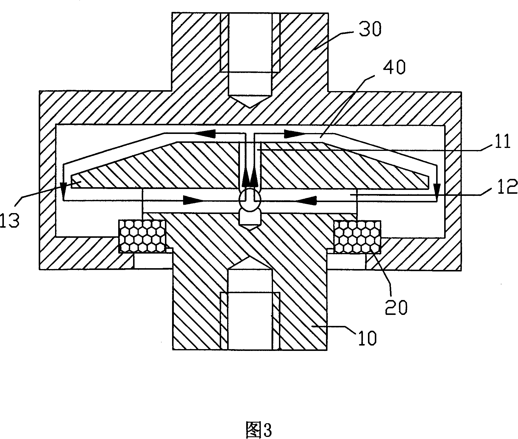
[0030] See accompanying drawing 2, the present invention comprises inner electrode 10, outer electrode 30 and metallized ceramic insulator 20, and the three are combined to form a closed space filled with inert gas, and a discharge gap 40 is arranged in this space, and inner electrode 10 One end is embedded in a closed gas space, and a central hole 11 and several air inlet holes 12 communicating with the central hole 11 are provided at the embedded end, among which the air inlet hole 12, the central hole 11 and the discharge gap 40 are formed Gas circulation path.

[0031] The central hole 11 is designed axially along the centerline, while the air inlet hole 12 is designed radially and communicates with the central hole 11 vertically.

[0032] The gas discharge device consisting of the above-mentioned components is provided with a closed gas circulation path inside, that is, a non-following cermet gas discharge tube.

[0033] When the above-mentioned no-following cermet gas d...


PUM


Abstract

This metal-ceramic gas discharge tube for unordered current after lightning stroke used for strong current system involves: inner electrode, outer electrode and metallized ceramic insulator. The three are combined to form a space filled with inert gas. In the space there are: discharging gap and one end of inner electrode. It also has central hole coaxial with said inner electrode and several gas-inlet holes connected to siad central hole. The gas inlet hole, central hole and discharging gap are combined to form a circulation loop. This invention solves problems such as: unordered flow in electric source of electronic device, and lightning stroke problem.

Description

Technical field: [0001] The invention relates to the technical field of discharge tubes, in particular to a cermet gas discharge tube without freewheeling after a lightning overvoltage in a high-voltage power supply system. Background technique: [0002] It is known that the cermet discharge tube, as a switching element that only depends on voltage, is widely used in electronic equipment signal systems to protect against lightning strikes and The damage caused by the overvoltage caused by electromagnetic pulse to electronic equipment; the application in the current electronic equipment power supply system is limited to equipotential isolation grounding, which is used to solve the problem caused by public grounding in the electronic equipment power supply and signal lightning strike overvoltage protection scheme. crosstalk interference problem. [0003] According to incomplete statistics, the metal-ceramic gas discharge tubes currently used around the world have a common def...

Claims


Application Information

Patent Timeline
Patent Type & Authority Patents(China)
IPC IPC(8): H01T1/15H01T4/00
Inventor 曾献昌
Owner GUANGZHOU HOPEWELL TECH
Why Eureka
Try Eureka