Filter press

A filter press and filter chamber technology, which is applied in filtration and separation, moving filter element filters, separation methods, etc., can solve the problems of difficult filter cloth replacement, complex automation control, and high replacement costs, and achieve simple and convenient operation monitoring and washing. The method is scientific and effective, and the effect of improving work efficiency

Inactive Publication Date: 2008-03-26
蒋卓冰
View PDF6 Cites 2 Cited by
  • Summary
  • Abstract
  • Description
  • Claims
  • Application Information

AI Technical Summary

Problems solved by technology

[0005] 1. Due to the structural characteristics of the filter plate itself of the existing plate and frame filter press, the existing plate and frame filter press is composed of a group of filter plates superimposed and arranged, and the number of filter chambers is large. The working process of the plate and frame filter press is in each filter chamber Simultaneously, and interfere with each other at the same time, the working efficiency of the whole machine depends on the working efficiency of individual filter chambers
[0006] 2. The large number of filter plates makes the number of parts of the whole machine huge, the automation control is complicated, and the working status of the filter chamber is difficult to detect
The volume change range of the filter chamber is limited by the diaphragm or filter plate sealing ring itself, resulting in limited volume change, limited service life of the diaphragm or filter plate sealing ring, and high replacement costs
[0008] 4. Filtration pressure and squeezing pressure have an effect and reaction with the sealing pressure of the filter chamber, and the kinetic energy consumption is huge
[0010] 6. The processing requirements of the filter cloth are high, it is difficult to use the filter cloth directly, it is difficult to replace the filter cloth of large-scale equipment, and the replacement of the filter cloth takes a long time

Method used


Image

  • Filter press
  • Filter press
  • Filter press

Examples


Embodiment

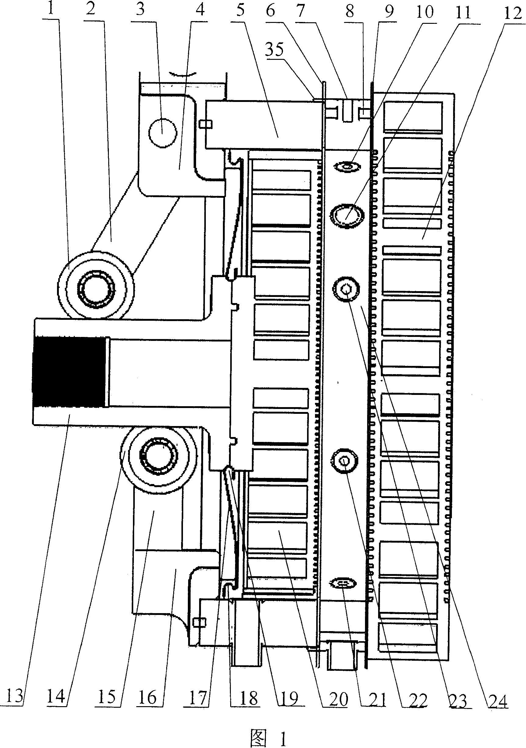
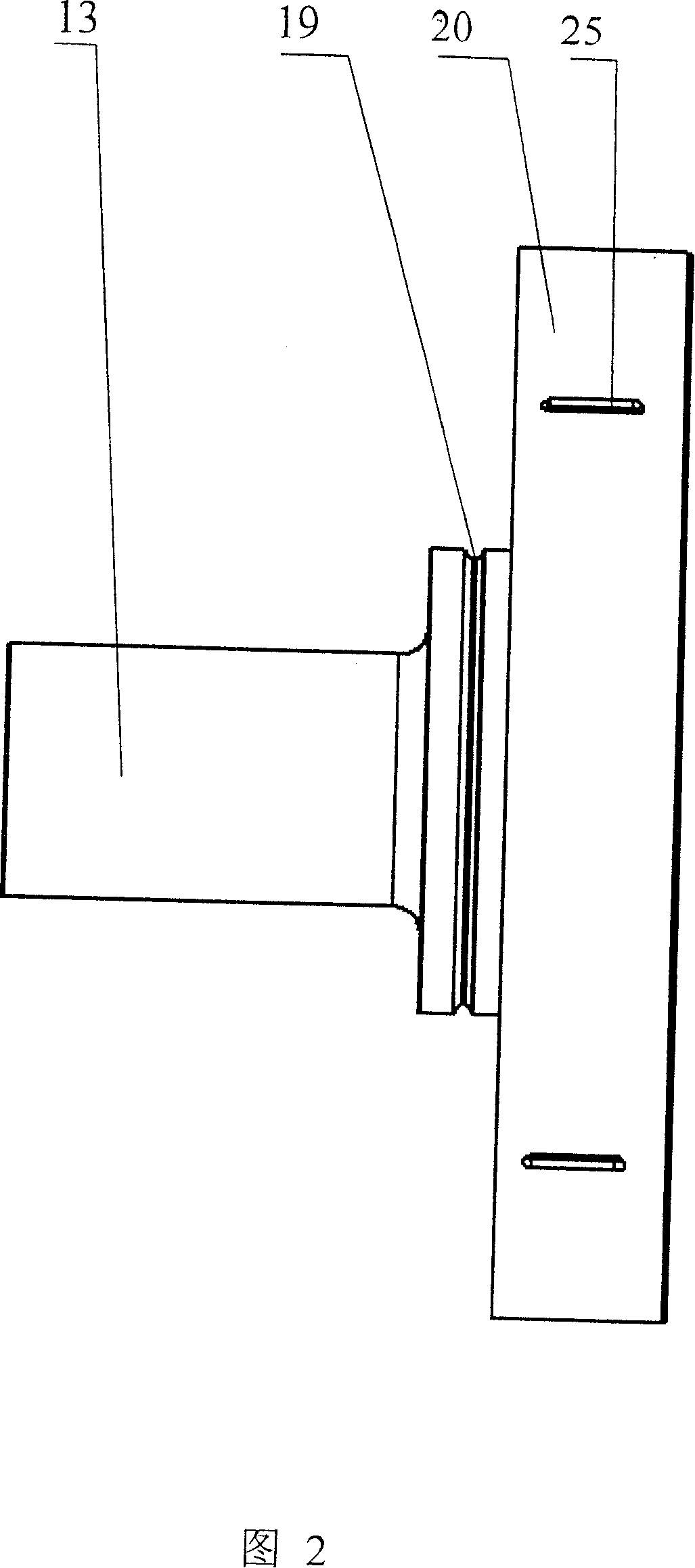
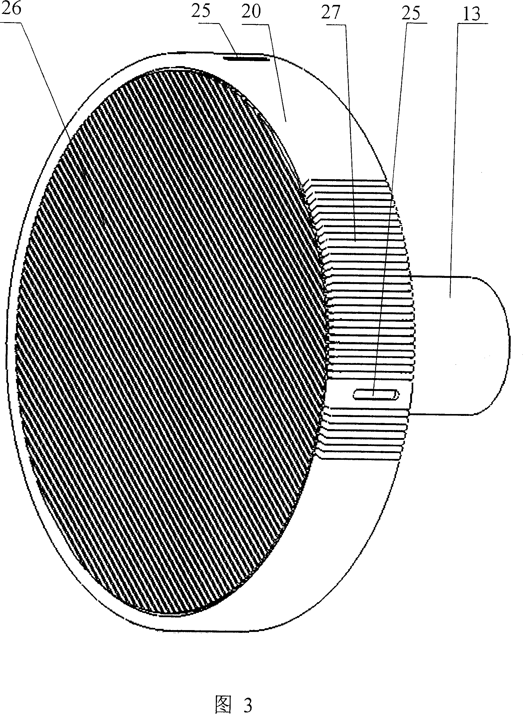
[0039] Example. Filter press combined with two single chamber machines

[0040] A filter press combined with two single-chamber machines, as shown in the accompanying drawings, it has a single-chamber machine, each single-chamber machine consists of a fixed filter plate 12, a multifunctional filter chamber 7, a moving frame 5 and The movable filter plate 20 is composed of at least three connecting rod installation holes 45 on the outer periphery of the fixed filter plate 12, and the fixed filter plate 12 has a left inlet liquid inlet 46, a left filtrate outlet 47 and a right inlet liquid inlet 48 , the right side filtrate outlet 49, the positive and negative sides of the fixed filter plate 12 each have a circle of fixed filter plate filter chamber sealing surface 43, and there are circular or The diamond-shaped particles constitute the drainage groove 44, which is a passage for fluid to enter and exit quickly. The plate filter cloth 9 is clamped and fixed, the filter chamber ...


PUM


Abstract

The invention relates to a pressure filter, which comprises a single straining chamber device formed by a fixing filter plate, a multifunctional straining chamber ring, a moving frame and a movable filter plate. Wherein, the fixing filter plate has a liquid inlet and a filtrate outlet and a ring to fix the sealing surface of filter plate straining chamber; the surface of fixing filter plate has liquid discharge grooves; the fixed filter plate straining chamber sealing surface and the straining chamber sealing surface of multifunctional straining chamber ring clamp the fixed filter plate filter cloth; another straining chamber sealing surface of multifunctional straining chamber ring and the sealing surface of moving frame fix the filter cloth of movable filter plate; the moving frame via the hydraulic system compresses the moving frame, the multifunctional straining chamber ring and fixing filter plate; the fixing filter plate, multifunctional straining chamber ring and the moving frame form the straining chamber; the movable filter plate can make piston movement inside the straining chamber; the side wall of multifunctional filter chamber ring has a feeding inlet; the surface and side surface of movable filter plate have liquid discharge grooves, while the back surface has guide rod; the hydraulic system via the guide rod pushes the movable filter plate forwards or backwards inside the straining chamber.

Description

technical field [0001] The invention relates to a filter press for solid-liquid separation. Background technique [0002] Filtration dehydration is a dehydration method that separates solid and liquid from the slurry composed of solid and liquid through a filter medium. At present, the plate and frame filter press is a machine to realize the solid-liquid separation of slurry. Because of its good airtightness, high filtration pressure, easy washing, and strong adaptability to slurry, it can be used in water treatment, metallurgy, coal washing, food, etc. , pharmaceutical, chemical, and other industries have been widely used. The working process of the existing plate and frame filter press is: [0003] Compress filter plate→feeding→filter cake pressing→filter cake washing→filter cake purging→unloading [0004] The disadvantages of the existing plate and frame filter press are: [0005] 1. Due to the structural characteristics of the filter plate itself of the existing plat...

Claims


Application Information

Patent Timeline
Patent Type & Authority Patents(China)
IPC IPC(8): B01D25/21
CPCB01D33/01
Inventor 蒋卓冰
Owner 蒋卓冰
Why Eureka
Try Eureka