
CT bulb tube oil-duct temperature wireless monitoring system

A wireless monitoring and bulb technology, applied in the direction of temperature control, control/regulation system, non-electric variable control, etc., can solve the problems of not adapting to the use environment, unable to detect oil circuit faults, unable to issue alarms from the bulb, and achieve observation. Intuitive and convenient, avoid temperature rise, avoid damage effect

Active Publication Date: 2008-06-18
HANGZHOU SAMWAY IMAGE SCI & TECH CO LTD
View PDF5 Cites 0 Cited by
  • Summary
  • Abstract
  • Description
  • Claims
  • Application Information

AI Technical Summary

Problems solved by technology

[0005] In order to overcome the disadvantages that the existing CT tube temperature detection system is not suitable for the specific use environment, cannot detect oil circuit faults, and cannot issue an alarm before the tube is damaged, the present invention provides a system suitable for retrofitting on the existing CT. , Timely alarm before the tube is damaged, CT tube oil circuit temperature wireless monitoring system with more comprehensive protection for the tube

Method used


Image

  • CT bulb tube oil-duct temperature wireless monitoring system

Examples


Embodiment 1

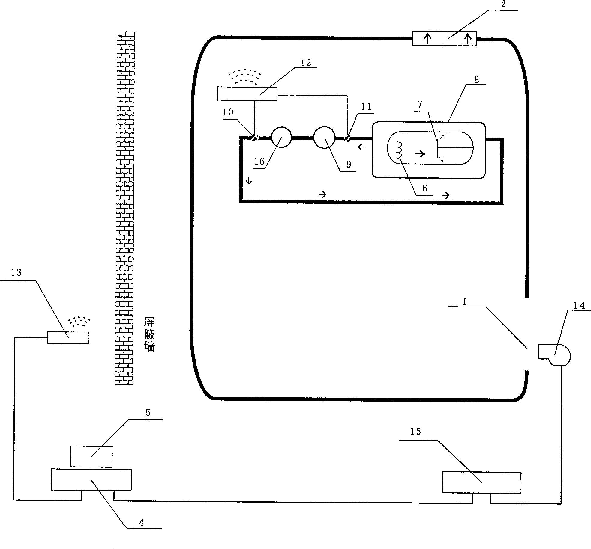
[0019] See the accompanying drawings: a wireless monitoring system for CT tube oil circuit temperature, including a frame with air inlet 1 and air outlet 2, a tube 3 installed in the frame, a computer 4 connected to the CT, and a computer connected to the computer. The display 5, the ball tube includes a heating filament 6 and a heavy metal target surface 7 sealed in the tube shell, cooling oil is arranged outside the tube shell, and the cooling oil circulates along the loop pipeline 8, and the loop pipeline is close to the tube shell An oil pump 9 is arranged at the oil pump, and a fan 16 is arranged at the return pipe at the rear of the oil pump. A first temperature sensor 10 is arranged on the return pipe behind the fan, and a second temperature sensor 11 is arranged on the return pipe between the ball tube and the oil pump. Described first temperature sensor 10, second temperature sensor 11 are connected with the wireless transmission processor 12 that transmits temperature...

Embodiment 2

[0025] Referring to accompanying drawing: the air inlet of frame is provided with air cooler 14, and described computer is provided with air cooler control unit, and described air cooler control unit 15 is connected with monitoring unit, when the first temperature sensor or the second temperature sensor When the temperature is within the set higher temperature value range, the control unit sends a signal to start the cooling fan.

[0026] Said upper upper temperature limit is lower than said normal upper temperature limit.

[0027] The operating temperature range of the preset air cooler, the air cooler starts when the upper limit is exceeded, and the cold air is sent into the rack to accelerate the heat exchange efficiency of the tube, and the air cooler stops operating when it is lower than the lower limit. The upper limit of the operating temperature range of the cooling fan is lower than the normal temperature upper limit, and the bulb tube is cooled in advance.

[0028] ...

Embodiment 3

[0030] The computer is connected with a voice reminding device, and the voice reminding device is connected with the monitoring unit. Voice alarm available.

[0031] The remaining structures and implementation methods of this embodiment are the same as those of Embodiment 2.


PUM


Abstract

A wireless temperature monitoring system for CT ball bulb oil line, comprising cradle, bulb, computer connected with CT, and display, the bulb comprising bulb shell, the out of which is equipped with cooling oil which flows in circle along circuit line, the circuit line is equipped with oil pump and fan, the circuit line in the back of fan is equipped with the first temperature sensor, the circuit line between the bulb and oil pump is equipped with the second temperature sensor, the temperature sensor is connected with wireless transmitting handler which is connected with computer, the computer is equipped with display unit which is used to display the temperature data in real time, and monitoring unit which is used to issue heat alarm, oil pump malfunction alarm, and fan malfunction alarm. The invention provides a wide alarm for the bulb temperature rising, which prevents the bulb damage; the users can observe temperature directly and conveniently, and can monitor the working condition of oil pump and fan, the device is suited to be installed in current CT.

Description

(1) Technical field [0001] The invention relates to a wireless monitoring system for the temperature of a CT ball tube oil circuit. (2) Background technology [0002] The inspection equipment CT (Computer Tomogrsphy) used in medical institutions uses X-rays as the radiation source. After sampling the radiation attenuation dose after penetrating the scanned object, the computer processes the data to generate an image of the scanned part. The ball tube is the X-ray emission source of CT. It is expensive and a lossy part. At present, only a few large foreign companies can produce it. my country's hospitals mainly rely on imports. The tube will generate a lot of heat while emitting X-rays, and the tube will be damaged the most when it is overheated, and the efficiency of heat dissipation directly affects the life of the tube. Conventional tubes use heating filament (cathode) to generate electrons, which are accelerated by a high-voltage electric field and bombard the heavy meta...

Claims


Application Information

Patent Timeline
Patent Type & Authority Patents(China)
IPC IPC(8): A61B6/03G05D23/00G05D27/00G01K17/00G08B21/18
Inventor 杨华
Owner HANGZHOU SAMWAY IMAGE SCI & TECH CO LTD
Learn More