
Vane of aerater

An aerator and impeller technology, which is applied in the field of rotary brush aerator impellers, can solve the problems of broken brushes, increased costs, and high manufacturing costs

Active Publication Date: 2008-07-02
中节能国祯环保科技股份有限公司
View PDF5 Cites 0 Cited by
  • Summary
  • Abstract
  • Description
  • Claims
  • Application Information

AI Technical Summary

Problems solved by technology

[0002] At present, the brush blades used in the impeller of the rotating brush aerator in the prior art are in the same plane as the axis of the rotating brush spindle, and the brush blades bear the normal shear force at the same time in the working state, which affects the service life of the blades; At the same time, the brushes used are formed by punching and bending steel plates, and the brushes are easily broken due to local stress; in the prior art of the impeller of the rotary brush aerator, about 8 to 16 brushes are connected with bolts to form a group. The pre-tightened deformation of the root of the brush and the rubber pad clamp the main shaft of the rotating brush to form an integral impeller structure, such as the technical solutions disclosed in Chinese patents CN2157188Y, CN2175226Y, and CN2216524Y. This depends on the deformation of the root of the brush to clamp the main shaft of the rotating brush. Structural scheme, it is very easy for the root of the brush to break. As long as the bolt connection part of any two adjacent brushes breaks, it will cause a group of integral impellers consisting of 8 to 16 brushes to fall into the sewage. ; Simultaneously, so many brush pieces are connected by bolts to transportation and installation, and maintenance has all brought great difficulties, and therefore greatly increase the cost, the brush piece molding process is complicated, and the manufacturing cost is high

Method used


Image

  • Vane of aerater
  • Vane of aerater
  • Vane of aerater

Examples


Embodiment Construction

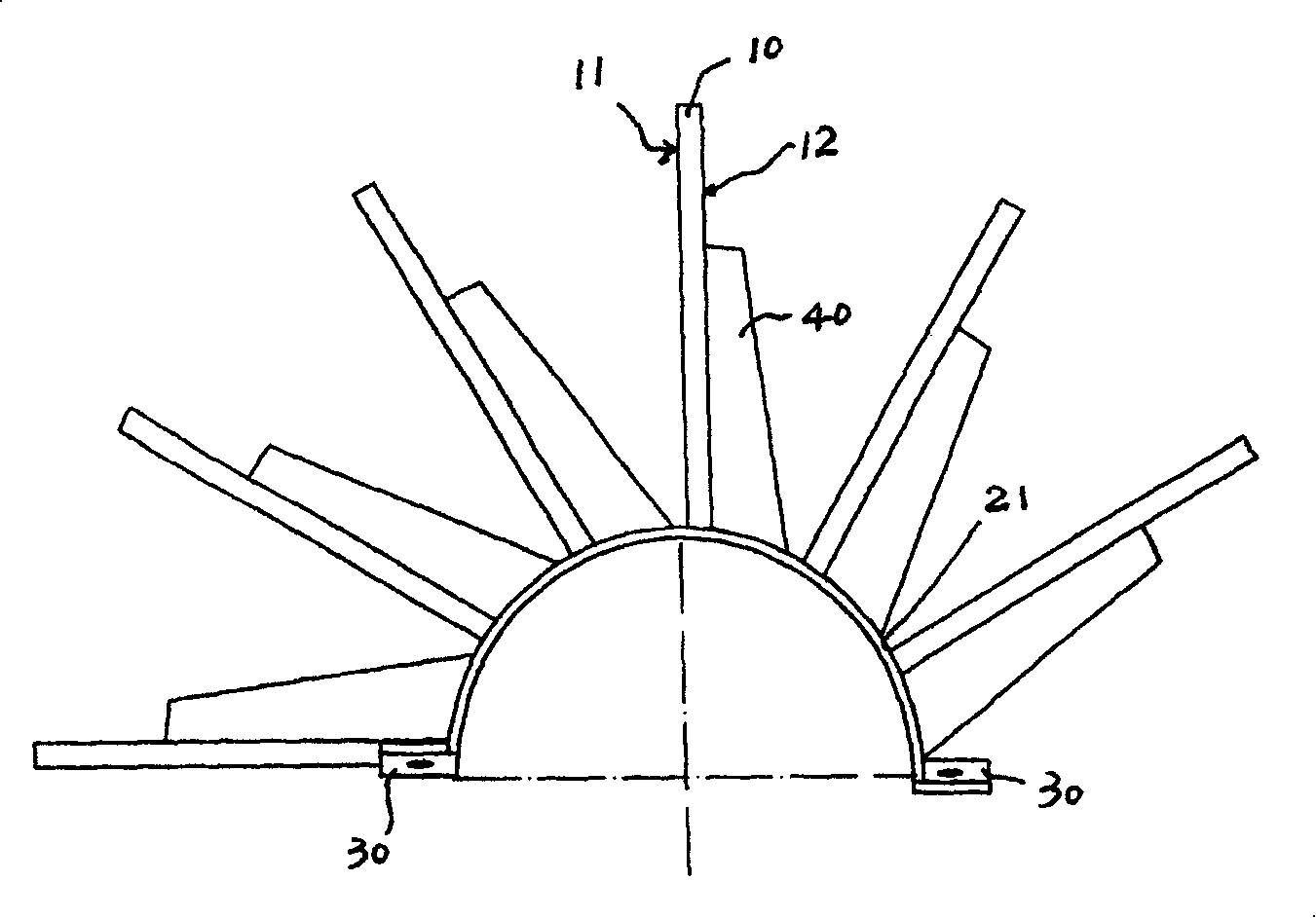
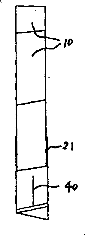
[0011] combine figure 1 , 2 , 3, the present invention adopts the form of a half impeller unit, and then combines to form a complete impeller assembly, and installs the impeller assembly on the main shaft of the rotating brush. The collar 20 , the brush piece 10 is welded and fixed on the outer surface of the collar unit 21 , and the head and tail of the half-shaft collar unit 21 are provided with a connecting plate 30 for connecting with another half-shaft collar unit 21 . There can be 2 to 4 half-shaft collar units 21, and the two-half structure is a more preferred form, that is, the impeller is composed of two independent half-shaft collar units 21 and the The half impeller unit composed of the brush slices 10 is combined, and the connecting plate 30 is connected by bolts. A rib plate 40 is provided between the backwater surface 12 of the brush piece 10 and the half shaft collar unit 21 . With the above structure, the phenomenon of stress concentration at the root of the...


PUM

PropertyMeasurementUnit
angleaaaaaaaaaa

Abstract

A blade wheel able to decrease the stress concentration at root of blade and elongate its service life is composed of an axle sleeve consisting of two axle semi-sleeves, a connection plate between two axle semi-sleeves, and several blades welded to the surface of axle sleeve.

Description

technical field [0001] The invention relates to the aeration equipment used in the urban sewage treatment process, more specifically to a new structure of the impeller of the rotating brush aerator. Background technique [0002] At present, the brush blades used in the impeller of the rotating brush aerator in the prior art are in the same plane as the axis of the rotating brush spindle, and the brush blades bear the normal shear force at the same time in the working state, which affects the service life of the blades; At the same time, the brushes used are formed by punching and bending steel plates, and the brushes are easily broken due to local stress; in the prior art of the impeller of the rotary brush aerator, about 8 to 16 brushes are connected with bolts to form a group. The pre-tightened deformation of the root of the brush and the rubber pad clamp the main shaft of the rotating brush to form an integral impeller structure, such as the technical solutions disclosed ...

Claims


Application Information

Patent Timeline
Patent Type & Authority Patents(China)
IPC IPC(8): C02F3/18C02F7/00
CPCY02W10/10
Inventor 许成法
Owner 中节能国祯环保科技股份有限公司
Learn More