
Electric tuning integrated optical filter with high-fineness

An optical filter and electrical tuning technology, applied in the coupling of optical waveguides, electromagnetic wave transmission systems, optics, etc., can solve the problems of slow electro-optical tuning filters, low spectral precision, large insertion loss, etc., and achieve spectral adjustment. Wide range, high spectral finesse, and easy-to-integrate effects

Inactive Publication Date: 2008-07-02
UNIV OF ELECTRONICS SCI & TECH OF CHINA
View PDF4 Cites 0 Cited by
  • Summary
  • Abstract
  • Description
  • Claims
  • Application Information

AI Technical Summary

Problems solved by technology

The F-P filter mainly adopts the optical fiber end face coating structure (also LiNbO 3 ), the piezoelectric ceramics are used to adjust the cavity length, the insertion loss is large, and the tuning range is small; the acousto-optic filter excites the sound wave in the optical waveguide (optical fiber or LiNbO 3 waveguide) and use the acoustic grating formed to diffract the optical mode to achieve tuning, the spectral precision is not high; the electro-optical tuning filter is slow and the adjustment is complicated; the fiber grating filter adopts electrode heating or electrostriction. Tuning (see literature: Optical filter using FBG temperature mechanical synthesis tuning technology, Acta Photonica Sinica, 2002, 31(12)), the central wavelength of the grating will change with temperature
Although various filters have certain research progress and practical possibilities, there are still deficiencies, which are caused by their principles and structures, and cannot be overcome

Method used


Image

  • Electric tuning integrated optical filter with high-fineness
  • Electric tuning integrated optical filter with high-fineness
  • Electric tuning integrated optical filter with high-fineness

Examples


Embodiment Construction

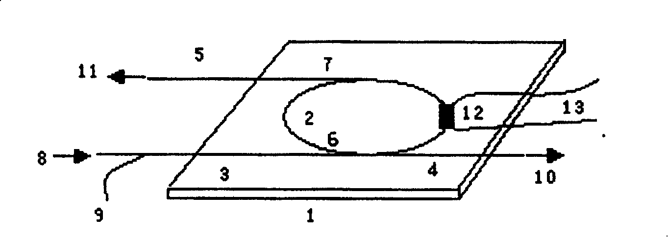
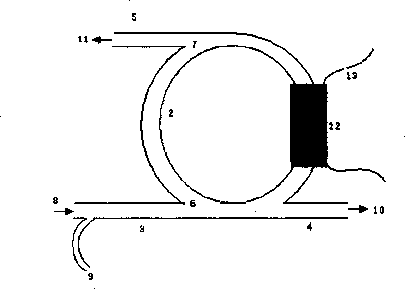
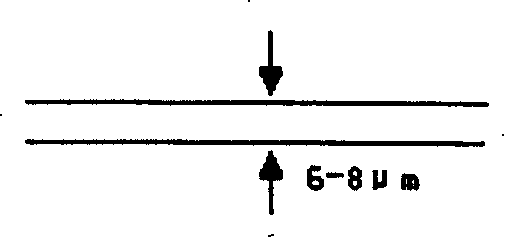
[0035] Selection: Straight waveguides 3, 4, 5 are 6-8 μm wide and 1-1.5 cm long; the refractive index of annular cavity 2 is about 1.5; the ellipse length of ring waveguide cross section is 6-8 μm, and the ellipse width is 4 μm; signal distribution in straight waveguide 1 The ratio to the straight waveguide 2 and the ring waveguide 3 is 5:95; the thickness of the heating resistor is 1 μm; the lead wire of the heating electrode is formed by pressure welding of gold wire or aluminum wire. According to the technical scheme of the present invention, a high-precision electronically tunable integrated optical filter is formed. After use, it can be known that the high-precision electronically tunable integrated optical filter provided by the present invention can achieve spectral fineness (kHz level).


PUM

PropertyMeasurementUnit
refractive indexaaaaaaaaaa

Abstract

The present invention discloses a high-accuracy electrically tuned integrated optical filter. It is characterized by that a ring cavity optical waveguide gyro and an integrated optical waveguide amplifier are combined together, namely, an active cavity with amplification medium can be used as optical waveguide ring cavity, and a cavity length regulator is added so as to form a new-type high-accuracy adjustable filter. Besides, said invention also provides its several advantages and its extensive application field.

Description

technical field [0001] The invention belongs to the technical field of electronic components, and in particular relates to the electric tuning integrated optical filter technology. Background technique [0002] As we all know, tunable optical filters have broad application prospects in the field of optical fiber communication. At present, the technologies related to tunable optical filters mainly include F-P filters, acousto-optic filters, electro-optic filters, etc. In addition, active semiconductors, tunable fiber gratings, and liquid crystals have also been researched on tunable filters (see literature: A tunable optical filter, patent No. 03128005, China; tunable optical filter, patent No. 98120842, China; a new type of F-P cavity optical filter, Journal of Nanjing University of Posts and Telecommunications, 2001, 21). The F-P filter mainly adopts the optical fiber end face coating structure (also LiNbO 3 ), the piezoelectric ceramics are used to adjust the cavity leng...

Claims


Application Information

Patent Timeline
Patent Type & Authority Patents(China)
IPC IPC(8): G02B6/26G02F1/35H04B10/12
Inventor 刘永智刘爽代志勇
Owner UNIV OF ELECTRONICS SCI & TECH OF CHINA
Learn More