Dying oscillation absorption spectrum detecting and sensing device for all optical fiber cavity

A technology of absorption spectroscopy and sensing devices, which is applied in absorption/scintillation/reflection spectroscopy, color/spectral characteristic measurement, spectrum investigation, etc., can solve the problems of low coupling efficiency, improvement of measurement sensitivity of fiber optic cavity ring-down sensing devices, and measurement sensitivity Advanced problems, to achieve the effect of low cost, wide spectral measurement range and high measurement sensitivity

Inactive Publication Date: 2008-07-09
SHANGHAI INST OF OPTICS & FINE MECHANICS CHINESE ACAD OF SCI
View PDF4 Cites 0 Cited by
  • Summary
  • Abstract
  • Description
  • Claims
  • Application Information

AI Technical Summary

Problems solved by technology

The disadvantage of this method is that the wavelength and bandwidth of the two fiber gratings used as a high reflection cavity mirror must be well matched. In addition, the spectral measurement range of this method is limited by the reflection bandwidth of the fiber grating, generally around a few nanometers
At the same time, the above-mentioned prior art also has a common shortcoming: the efficiency of coupling the incident light pulse into the fiber resonator depends on the reflectivity of the input cavity mirror, the higher the reflectivity, the lower the coupling efficiency, and the higher the light intensity entering the photodetector. Weak, and photodetectors have lower detection limits. On the other hand, it is known from formula 1 that the higher the reflectivity of the cavity mirror, the longer the cavity ring-down time, and the higher the measurement sensitivity
That is to say, there is a contradiction between the reflectivity of the cavity mirror and the input coupling efficiency, which limits the further improvement of the measurement sensitivity of the optical fiber cavity ring-down sensing device

Method used


Image

  • Dying oscillation absorption spectrum detecting and sensing device for all optical fiber cavity
  • Dying oscillation absorption spectrum detecting and sensing device for all optical fiber cavity
  • Dying oscillation absorption spectrum detecting and sensing device for all optical fiber cavity

Examples


Embodiment 1

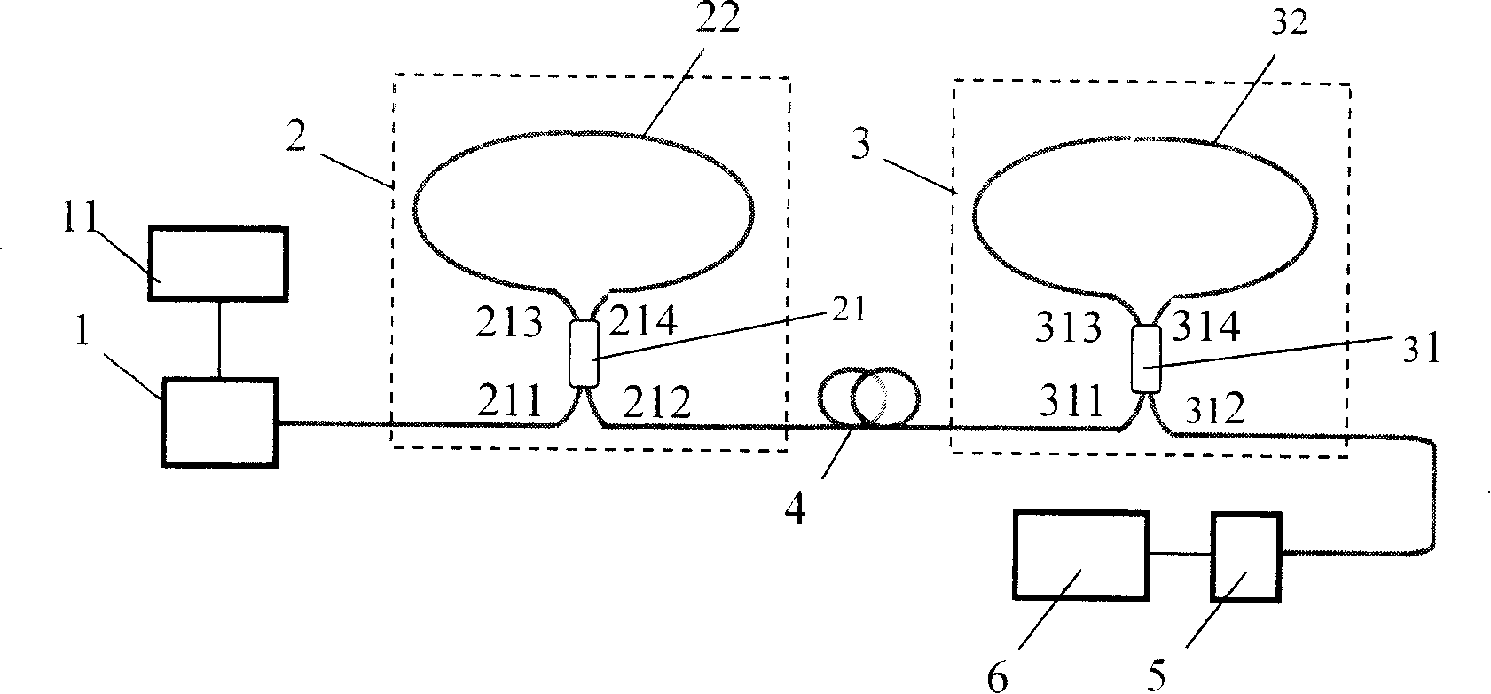
[0029] like figure 1 As shown, the all-fiber cavity ring-down absorption spectrum detection sensor device is composed of a light source 1 and its first driver 11, a fiber resonant cavity, a photodetector 5 and a signal acquisition and processing system 6 connected in sequence.

[0030] Described fiber resonant cavity is formed by the first fiber optic loop mirror 2 being connected with the second fiber optic loop mirror 3 through optical fiber 4; Described first fiber optic loop mirror 2 is formed by the third port 213 on the same side of the first fiber coupler 21 and The fourth port 214 is connected to the first fiber loop 22; the second fiber loop mirror 3 is connected to the second fiber loop 32 by the third port 313 and the fourth port 314 on the same side of the second fiber coupler 31 Composition; the output end of the light source 1 is connected to the first port 211 of the first fiber coupler 21, and the second port 212 of the first fiber coupler 21 is connected to on...

Embodiment 2

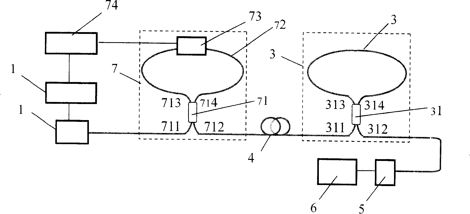
[0034] like figure 2 As shown, the all-fiber cavity ring-down absorption spectrum detection and sensing device of the present invention, the fiber resonator is connected to the first port 311 of the second fiber coupler 31 by the second port 712 of a ring mirror switch 7 through the optical fiber 4 Composition, the second fiber loop mirror 3 is formed by connecting the third port 313 and the fourth port 314 on the same side of the second fiber coupler 31 with the second fiber loop 32; the output end of the light source 1 is connected to the The first port 711 of the ring mirror switch 7 is connected; the second port 712 of the ring mirror switch 7 is connected to one end of the optical fiber 4; the other end of the optical fiber 4 is connected to the first port 311 of the second fiber coupler 31, the The second port 312 of the second optical fiber coupler 31 is connected to the signal acquisition and processing system 6 via the photodetector 5 . The composition of the ring m...

Embodiment 3

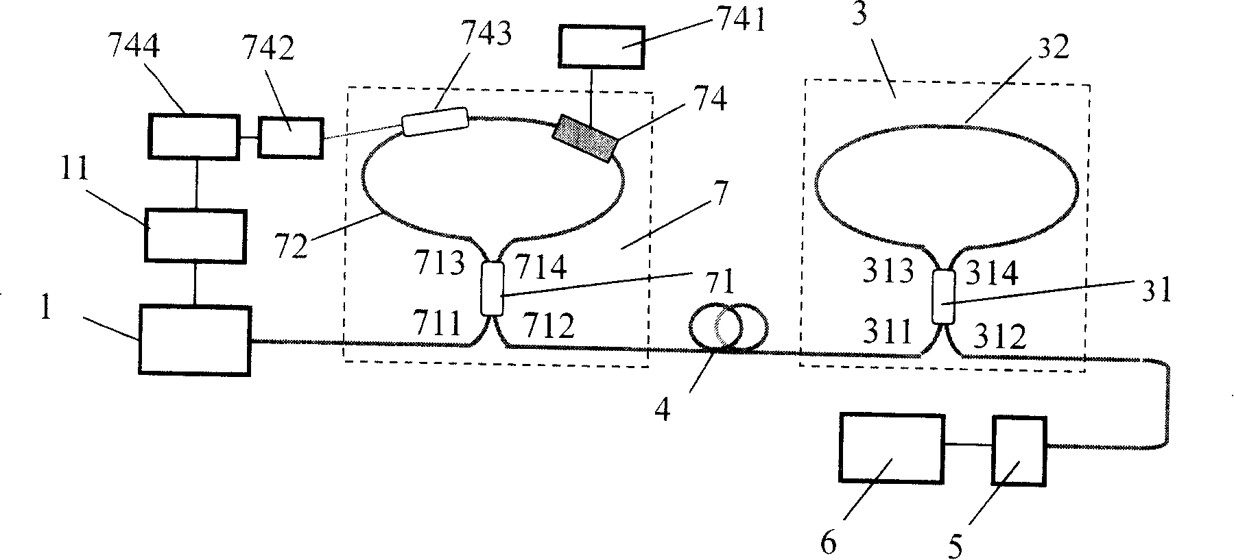
[0040] image 3 Embodiment 3 of the present invention: a schematic diagram of an optical fiber cavity ring-down sensing device that uses a nonlinear optical fiber loop mirror composed of a semiconductor optical amplifier to realize high-speed switching between high reflection and high transmission characteristics;

[0041] Among the figure: 74 is a semiconductor optical amplifier, and 741 is its second driving power supply. The semiconductor optical amplifier 74 not only has the function of light amplification, but also changes the effective refractive index due to optical nonlinear effects under different incident light intensities. 742 is a control laser. The pulsed laser signal it sends is injected into the third fiber loop 72 through the third fiber coupler 743. 744 is the third driving power for controlling the pulse operation of the laser 742, and its pulse frequency and phase are synchronized with the signal light source 1 and can be adjusted.

[0042] The working pri...


PUM


Abstract

The invention relates to a device for detecting the total optical fiber absorbing spectrum, which comprises an illuminating source, the first driver, an optical cavity, a light-sensitive detector, and a signal collecting and processing system connected together. The device has the merits as follows: the reflectance of the cavity is high, the fineness of the resonant cavity is high, the reflection bandwidth and spectral measuring range are wide, the luminous power couple is efficiency, the measuring sensibility is high and the structure is simple.

Description

technical field [0001] The invention is an optical fiber detection and sensing technology adopting the principle of cavity ring down. The invention belongs to the technical field of optical measurement and sensing, and is mainly applied to the sensing and detection of physical quantities such as strain, pressure and current, and chemical quantities such as liquid and gas concentration and refractive index. Background technique [0002] Optical fiber sensors have many advantages such as strong anti-electromagnetic interference, high sensitivity, good electrical insulation, safety and reliability, corrosion resistance, and can form an optical fiber sensor network, so they have broad applications in various fields such as industry, agriculture, biomedicine, and national defense. Application prospect. [0003] Cavity Ring Down Spectroscopy (Cavity Ring Down Spectroscopy) is a new type of absorption spectroscopy detection technology developed in recent years. The basic principl...

Claims


Application Information

Patent Timeline
Patent Type & Authority Patents(China)
IPC IPC(8): G01J3/42G01N21/25
Inventor 蔡海文瞿荣辉方祖捷王允韬
Owner SHANGHAI INST OF OPTICS & FINE MECHANICS CHINESE ACAD OF SCI
Why Eureka
Try Eureka