Heat pump device
A technology of heat pump device and decompression device, which is applied to fluid heaters, lighting and heating equipment, refrigeration safety arrangements, etc., can solve the problems of insufficient compression, vibration and wear of cold catalyst tubes, etc., to reduce product cost, The effect of improving reliability
- Summary
- Abstract
- Description
- Claims
- Application Information
AI Technical Summary
Problems solved by technology
Method used
Image
Examples
Embodiment approach 1
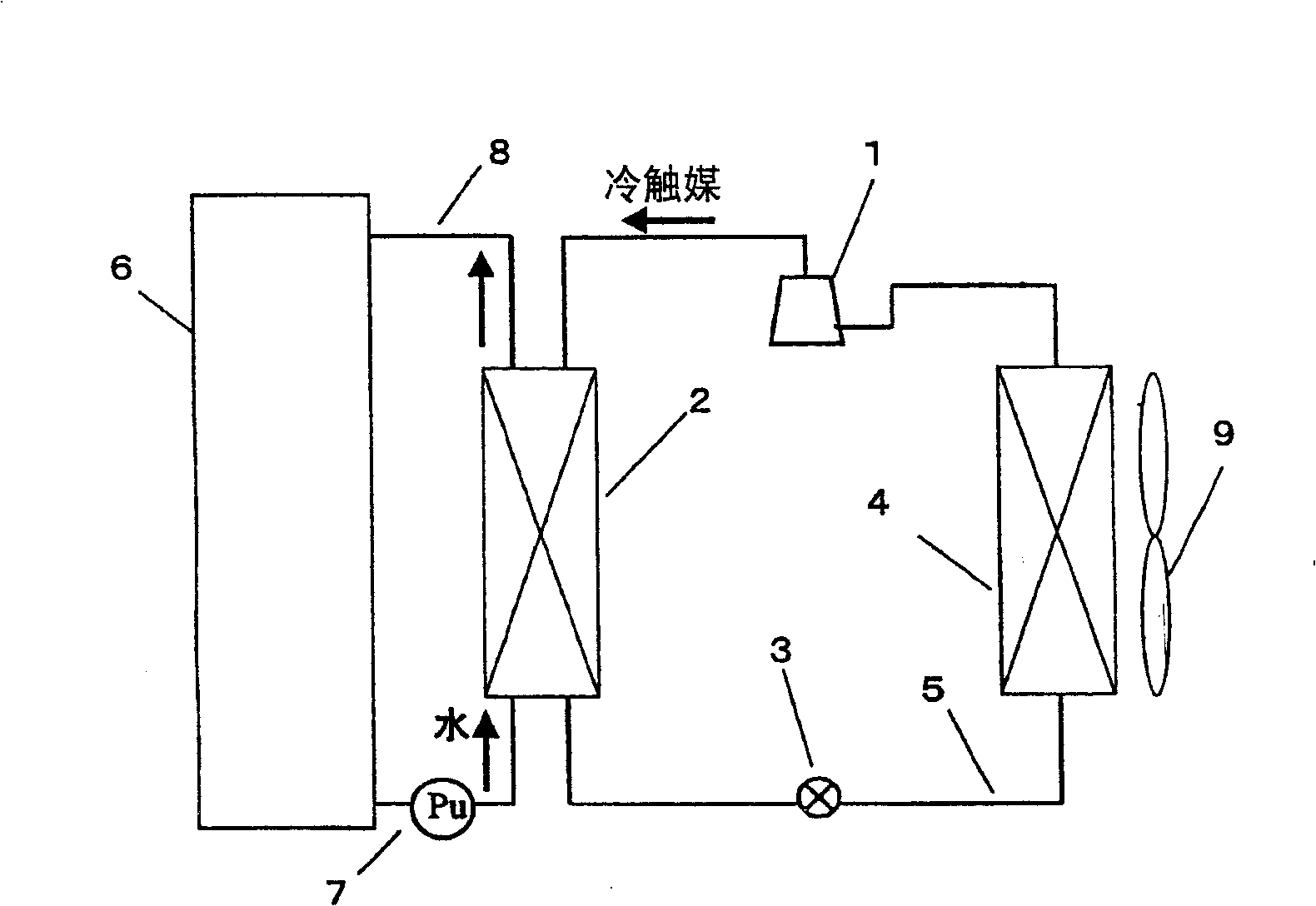
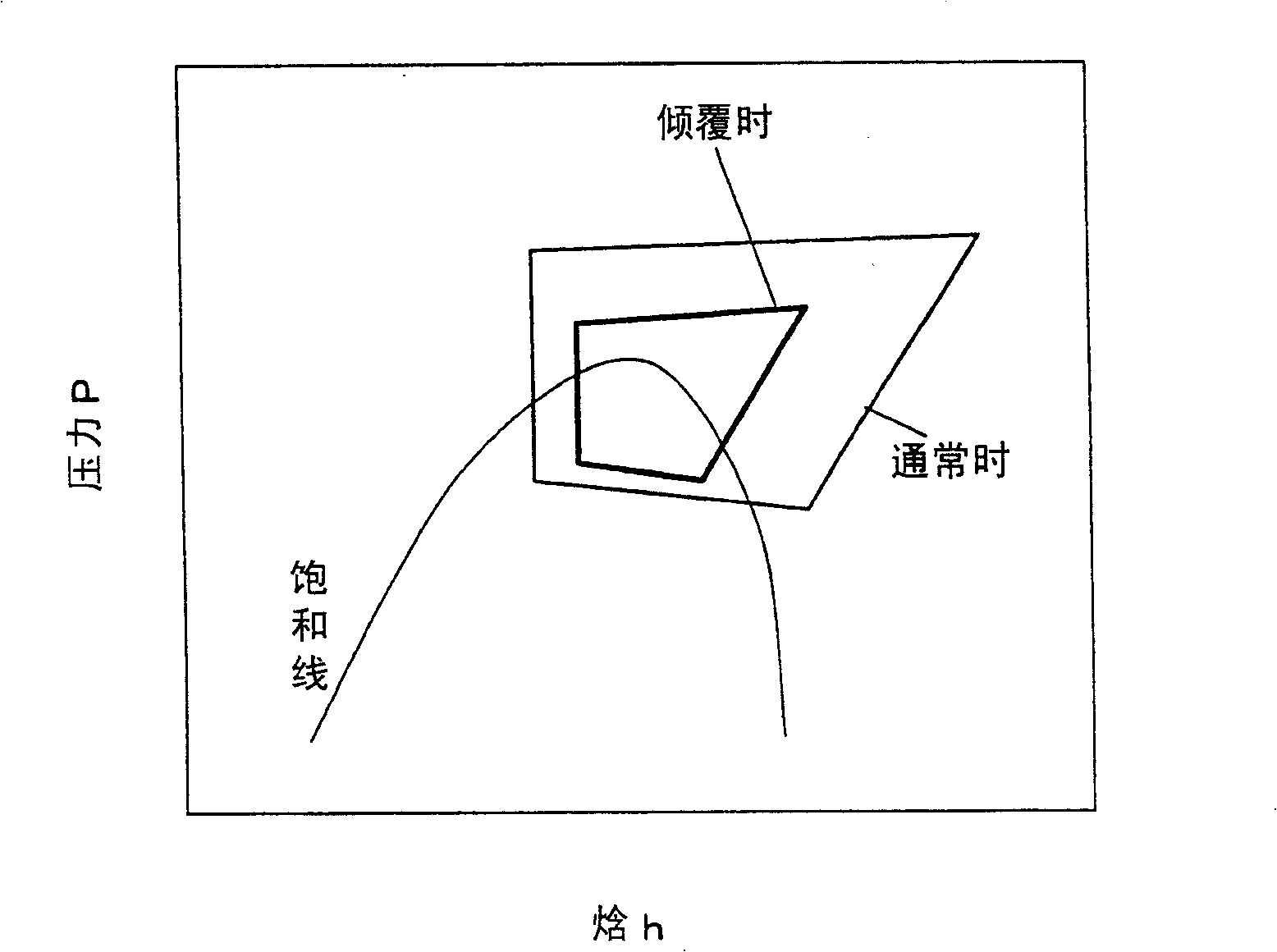
[0033] figure 1 A configuration diagram showing a heat pump device according to Embodiment 1 of the present invention, particularly a hot water supplier. in addition, figure 2 It is a Mollier diagram showing the operation of the heat pump device according to the present embodiment during the normal state and when the scroll compressor is overturned. The heat pump circuit connects the scroll compressor 1, the heat exchanger 2 for hot water supply, the decompression device 3, and the evaporator 4 through the cold catalyst pipe 5 to circulate the cold catalyst. Near the evaporator 4, a blower device is installed to change the evaporator capacity of the heat pump circuit. In this heat pump circuit, it is set to use carbon dioxide as a cold catalyst and operate with the high pressure side exceeding the critical pressure.
[0034]In addition, the hot water storage circuit is connected to the hot water storage tank 6 and the heat absorber 2 by the water pipe 8, and the water is ...
Embodiment approach 2
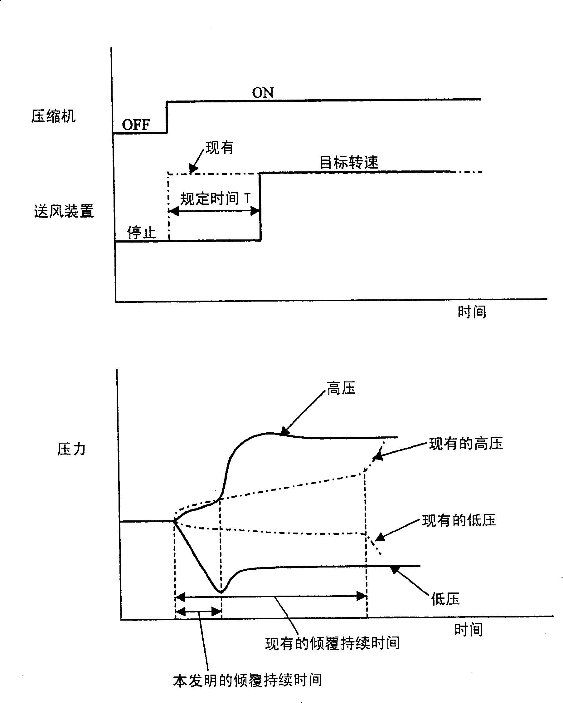
[0041] Figure 4 Showing a heat pump device according to Embodiment 2 of the present invention, Figure 5 It is a time chart of the high and low pressure of the air supply device and the refrigeration cycle when the heat pump device is started.
[0042] In this embodiment, a cold catalyst pressure detecting device (for example, a pressure sensor) 10 for detecting the pressure of the cold catalyst sucked in the scroll compressor 1 is arranged on the cold catalyst pipe 5 between the scroll compressor 1 and the decompression device 4 ,Such as Figure 5 As shown, the control is performed so that after the scroll compressor 1 is started, the blower 9 is stopped until the cold catalyst pressure detected by the cold catalyst pressure detection device 10 reaches a predetermined pressure (P), and the air blower 9 is stopped when the pressure reaches the predetermined pressure (P). After P) below, start the blower 9. That is to say, the predetermined pressure (P) of the cold catalyst...
Embodiment approach 3
[0044] Figure 6 shows a heat pump device according to Embodiment 3 of the present invention, except that Figure 4 In addition to the shown configuration, an outside air temperature detection device (for example, a temperature sensor) 11 for detecting the outside air temperature is provided.
[0045] When the outside air temperature detected by the outside air temperature detection device 11 is below a predetermined temperature, the same control as that of Embodiment 2 is performed, and when the outside air temperature exceeds a predetermined temperature, control is performed so that after the scroll compressor 1 starts, Even if the cold catalyst pressure detected by the cold catalyst pressure detection device 10 falls below a predetermined pressure (P), the air blower 9 is activated after a predetermined time (T) has elapsed since the scroll compressor 1 was started.
[0046] Due to such control, even when the outside air temperature is high and the pressure of the evaporat...
PUM
 Abstract
Description
Claims
Application Information
 - R&D
- Intellectual Property
- Life Sciences
- Materials
- Tech Scout
- Unparalleled Data Quality
- Higher Quality Content
- 60% Fewer Hallucinations
Browse by: Latest US Patents, China's latest patents, Technical Efficacy Thesaurus, Application Domain, Technology Topic, Popular Technical Reports.
© 2025 PatSnap. All rights reserved.Legal|Privacy policy|Modern Slavery Act Transparency Statement|Sitemap|About US| Contact US: help@patsnap.com


