Intellective economizer for street lamp

A technology for smart street lamps and power savers, applied in electric light sources, electrical components, energy-saving lighting, etc., can solve problems such as increased self-consumption loss, watt-hour meter errors, and drive circuit failures, so as to prolong the service life and simplify the drive circuit , The effect of low-power drive

Inactive Publication Date: 2008-11-12
上海绿能高科环保节能科技有限公司
View PDF4 Cites 0 Cited by
  • Summary
  • Abstract
  • Description
  • Claims
  • Application Information

AI Technical Summary

Problems solved by technology

Its disadvantage is that the harmonics generated by itself will interfere with the power grid and other electrical equipment, causing noise in the lamps, so there is a loss of electric energy other than light energy, resulting in errors in the watt-hour meter
Because the magnetic latching relay is closed or released, we cannot know, for example, it is stuck or stuck, or it is not driven, or the drive circuit fails.
The relay SW1 / SW2 is operated by a contactor or a relay, and the action time it needs is 5-20ms, that is to say, the opening of SW1 and the closing of SW2 cannot be completed at the same time, and there will always be some differences
Even the control circuit cannot do this precisely
In this way, during the switching process, there will be no power on the load for 5-20ms, and the load will have a short-term power supply interruption, causing the lamp to go out briefly, and it needs to be restarted, or even cannot be restarted due to the drop in voltage.
Cause the lamp to flicker for a long time and cannot emit light normally
The ordinary contactor it uses is not only large in size and high in weight, but also increases the self-consumption loss
[0003] The magnetic latching relay in the above-mentioned prior art relies on the magnetic field generated by the wire pack to drive the on-off of the contacts, and the closing or opening of its contacts is realized by the reverse or forward voltage applied to the wire pack, and is controlled by It is maintained by the permanent magnet inside, and at the same time, the forward or reverse current must be passed all the time, so that the wire package is in a state of heating for a long time and consumes electric energy, shortening the life of the magnetic latching relay

Method used


Image

  • Intellective economizer for street lamp
  • Intellective economizer for street lamp
  • Intellective economizer for street lamp

Examples


Embodiment Construction

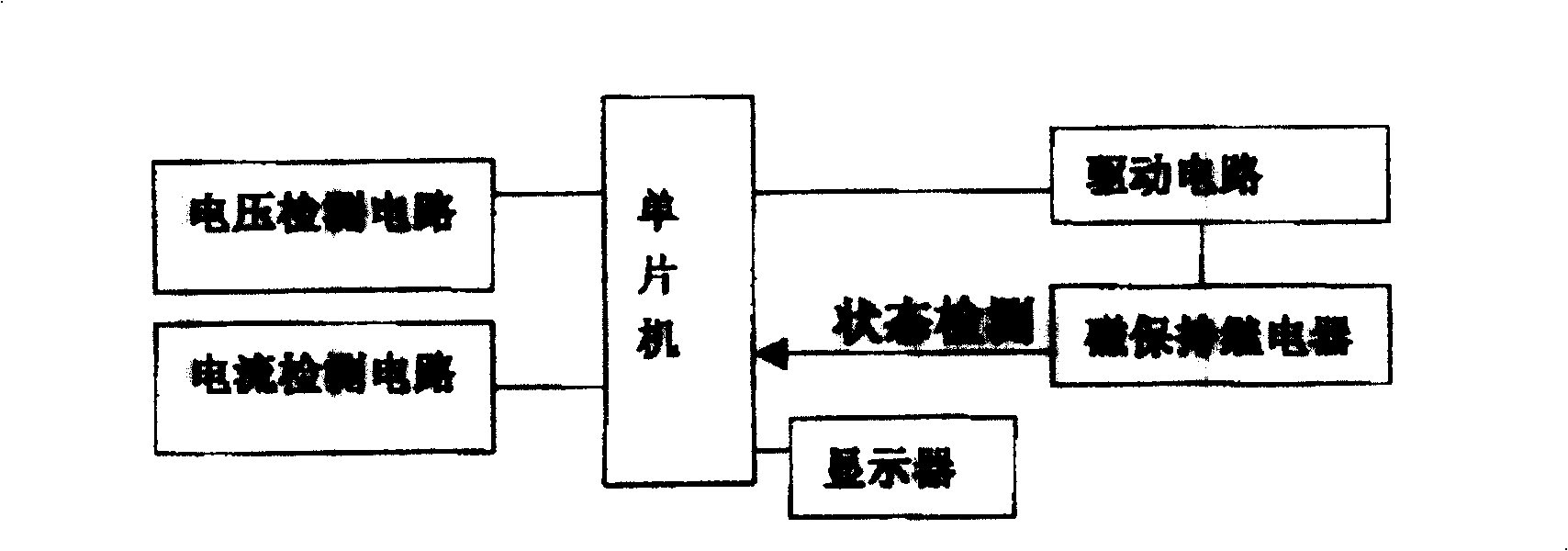
[0017] Figure 1 to Figure 4 An embodiment based on improvements and developments of the prior art is described. exist figure 1 Among them, the voltage detection circuit and current detection circuit connected to the single-chip microcomputer and the A / D converter (not shown) connected thereto are conventional technologies. Wherein the single-chip microcomputer can be the single-chip microcomputer of 51 series, the single-chip microcomputer of the present embodiment can be AT8C51, and the A / D converter can be more than 8 but not limited to be ADC0809.

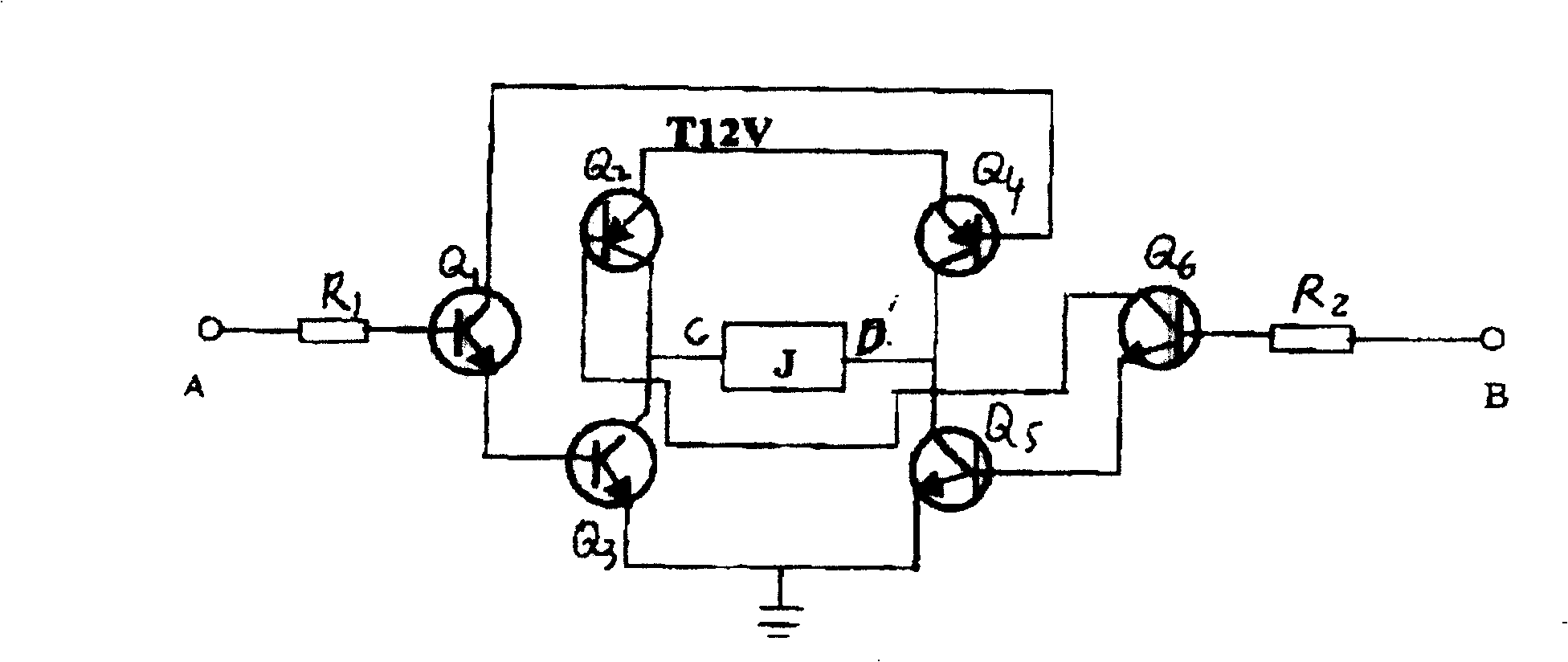
[0018] figure 2 The shown driver circuit is generally composed of six transistors, and the input terminal A point of the resistor R1 may be electrically connected with a gate circuit, which is the prior art (not shown). When a high level (+5V) is applied to point A, the transistors Q1, Q3, and Q4 are turned on, and the current from T12V, Q4 passes through the magnetic latching relay J connected in parallel between Q2, Q3, Q...


PUM


Abstract

The invention is applicable to street lamp, sodium lamp and halogen lamp. The economizer includes detection circuit of voltage and current connected to single chip, parallel subassembly of tapping relay of transformer connected to single chip and drive circuit. Relay SWR and resistance R are connected to the parallel subassembly of magnetic latching relay in parallel. The magnetic latching relay detects and controls current and voltage fed to lamp, making transformer be switched smoothly, and driving be stopped after action of contactor. The invention solves issue that it is not sensed that whether the magnetic latching relay is started up or not. Advantages are: each part works at large current only in short time period so as to lower consumption, reduce heat and prolong service life.

Description

technical field [0001] The invention relates to a street lamp power saver mainly used for street lamps, ordinary fluorescent lamps, sodium lamps, metal halide lamps and other lighting equipment. Background technique [0002] Experiments have proved that the light emitted by a lamp is not directly proportional to the power fed to the lamp. This is due to the noise emitted by the ballast in the lamp, and the heating of the lamp tube does not contribute much to the light emission, but part of the electric energy is lost in the form of sound energy and heat energy. And the heating of the lamp tube will also aggravate the aging of the lamp tube. At present, there are roughly three kinds of lighting energy-saving appliances in the known technology. One is to use the method of controlling voltage and current to achieve optimal control. The other is to use thyristor circuit control to achieve power saving. Its disadvantage is that the harmonics generated by itself will interfere...

Claims


Application Information

Patent Timeline
Patent Type & Authority Patents(China)
IPC IPC(8): H05B41/36H05B41/14
CPCY02B20/72
Inventor 程明
Owner 上海绿能高科环保节能科技有限公司
Why Eureka
Try Eureka