Inverting time control method for heat accumulation type burner

A technology of reversing time and combustion devices, which is applied in the direction of control of combustion, lighting and heating equipment, indirect carbon dioxide emission reduction, etc., can solve problems such as unbearable smoking equipment, complex industrial furnace structure, damage to furnace doors and other equipment, and achieve reduction Reduce energy consumption, improve temperature control accuracy, and ensure normal operation

Active Publication Date: 2008-12-31
CHONGQING AOKEQI TECH
View PDF10 Cites 1 Cited by
  • Summary
  • Abstract
  • Description
  • Claims
  • Application Information

AI Technical Summary

Problems solved by technology

[0006] 1. If all the flue gas is discharged from the heat storage body, the temperature of the heat storage body will continue to rise, and the exhaust gas temperature will continue to rise, which will eventually cause the exhaust gas temperature to be too high, which is unbearable for the smoking equipment
[0007] 2. No additional smoke exhaust device is installed, and the exhaust temperature is controlled so that part of the smoke is not discharged from the heat storage body. As a result, the furnace pressure is too high, and the excess smoke is naturally discharged from the gaps such as the furnace door, which is easy to cause the furnace door to be damaged. equipment damage
[0008] 3. Add additional discharge devices, such as flue and chimney, which complicates the structure of industrial furnaces, increases construction costs, and increases the difficulty of control

Method used


Image

  • Inverting time control method for heat accumulation type burner
  • Inverting time control method for heat accumulation type burner

Examples


Embodiment Construction

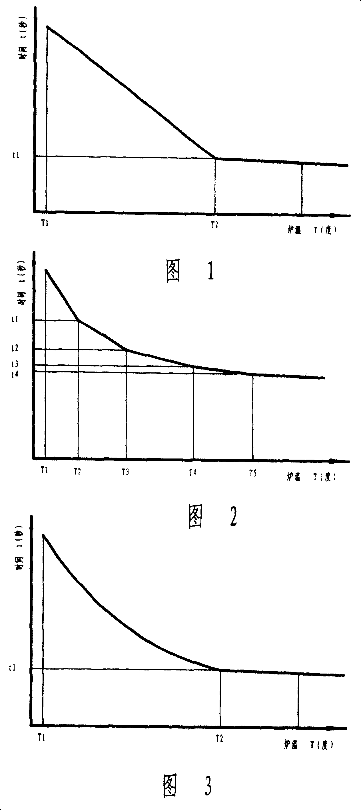
[0027] As shown in Figure 1, a schematic diagram of the relationship between the commutation time and the furnace temperature of the present invention, the commutation time when the two burners of the regenerative combustion device burn in turn, after the regenerative combustion device is ignited and burned, the two burners burn in turn As the temperature of the furnace increases, the commutation time is gradually shortened; when a certain set temperature is reached, the commutation time changes little and remains basically constant. Since the two burners burn in turn, in order to ensure the balance of combustion, the change of the reversing time should ensure the combustion cycle of the two burners, which is an even multiple of the combustion cycle of the two burners.

[0028] As shown in Figure 1, a schematic diagram of the first embodiment of the relationship between reversing time and furnace temperature of the present invention, the reversing time and furnace temperature are ...


PUM


Abstract

The invention discloses a method for controlling the steering time in thermal-accumulated burner. The invention is characterized in that when the thermal-accumulated burner is ignited, the burning time of two nozzles are reduced stepped along the temperature increase of furnace. Compared with present technique, the invention can reduce the steering time along the optimized curvature according to the temperature increase of the furnace, to control the air and fuel temperatures, reduce the flame temperature, and improve the temperature-control accuracy. With the increase of furnace temperature, the steering time is reduced stepped, to improve the control accuracy from +-5 Deg. C to +-1 Deg. C to reach the control level of electric furnace. And at the high temperature, the invention can reduce the flame temperature to confirm the control accuracy. At the low temperature, the invention can improve the temperature of accumulator to improve the preheat temperatures of air and gas, to improve the heating efficiency. The invention can reduce the energy consumption.

Description

Technical field [0001] The invention relates to a control method of a regenerative combustion device, in particular to a reversing time control method for controlling the alternate combustion time of two burners of the regenerative combustion device. Background technique [0002] The regenerative combustion device uses a pair of regenerative pulse burners A and B whose combustion volume is proportional to the exhaust gas volume to recover the waste heat of the high-temperature flue gas produced by combustion. When the burner A on one side burns, the burner B on the other side sucks and exhausts the high-temperature flue gas in the furnace. The high-temperature flue gas exchanges heat energy with the heat storage body when passing through the burner heat storage body. The temperature of the heat-absorbed and high-temperature flue gas is reduced, and is finally discharged. After a certain period of time, the combustion direction is reversed, and burner B burns. The cold air or gas ...

Claims


Application Information

Patent Timeline
Patent Type & Authority Patents(China)
IPC IPC(8): F23N5/20F27B14/20
CPCY02E20/34
Inventor 顾向涛
Owner CHONGQING AOKEQI TECH
Why Eureka
Try Eureka