Permanent-magnet and turbine composite bearing

A turbo compound and bearing technology, applied in the direction of bearings, shafts and bearings, mechanical equipment, etc., can solve the problems of magnetic levitation bearings, such as complex structure, small bearing capacity per unit volume, and limited application, so as to achieve enhanced relative suspension force and bearing capacity per unit volume The effect of large capacity and broadened application range

Inactive Publication Date: 2009-02-11
刘新广
View PDF4 Cites 0 Cited by
  • Summary
  • Abstract
  • Description
  • Claims
  • Application Information

AI Technical Summary

Problems solved by technology

[0004] The purpose of the present invention is to solve the problems of existing magnetic suspension bearings, such as complex structure, small bearing capacity per unit volume, poor stability during high-speed operation, and limited application, and designs a permanent magnet and turbine composite bearing with compact structure, high rigidity, and unit Large volume bearing capacity, high operation stability and wide application

Method used


Image

  • Permanent-magnet and turbine composite bearing
  • Permanent-magnet and turbine composite bearing
  • Permanent-magnet and turbine composite bearing

Examples


Embodiment approach 1

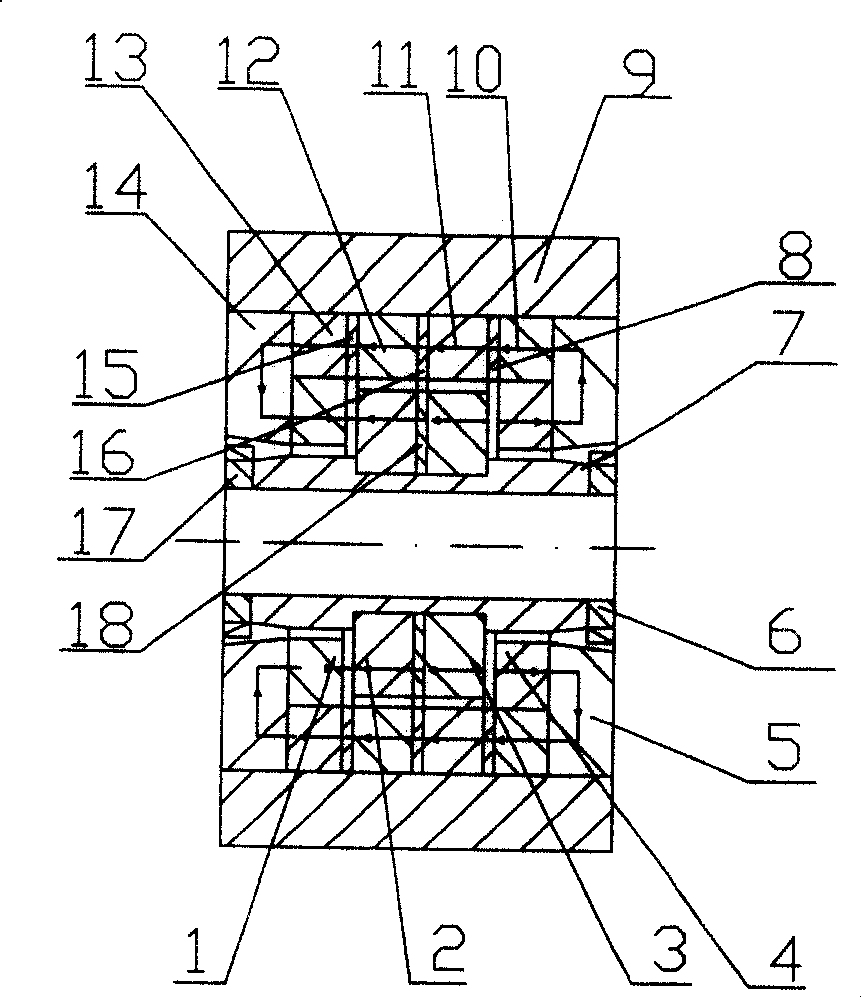
[0031] Implementation mode 1: if figure 1 As shown, the axially magnetized permanent magnet inner magnetic ring 2 and the inner magnetic ring 3 are fixed on the non-magnetic sleeve 7 of the supporting shaft. Between the inner magnetic ring 2 and the inner magnetic ring 3, there is a magnetically conductive spacer 18 of appropriate thickness, the size of its inner circle is the same as that of the inner magnetic ring, and the diameter of its outer circle is smaller than that of the inner magnetic ring on each side. One point (not shown in the figure), to strengthen the radial component magnetic force on the outer circle of the two ends of the inner magnetic ring 2 and the inner magnetic ring 3; If the magnetic force is large enough, the outer circle of the magnetic pad 18 can be made the same size as the outer circle of the inner magnetic ring. A turbine 6 and 17 are fixedly sleeved at both ends of the non-magnetic shaft sleeve 7, and the sleeve, the turbine, and the inner mag...

Embodiment approach 2

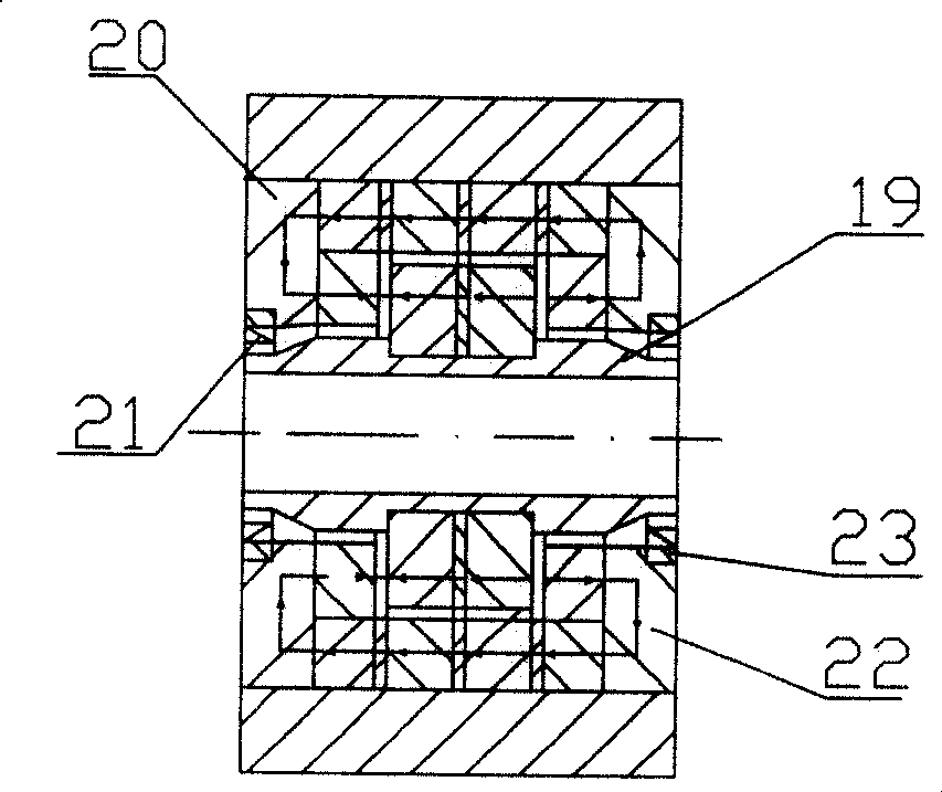
[0038] Implementation mode 2: if figure 2 Show. When the outer sleeve of the bearing needs to be rotated and the inner sleeve is fixed, the non-magnetic rotating sleeve 7, the magnetically conductive disks 5 and 14, and the turbines 6 and 17 in Embodiment 1 are correspondingly changed into figure 2 Shown non-magnetic rotating sleeve 19, magnetic conduction disk 20 and 22, turbine 21 and 23, and turbine 21 and 23 are fixedly connected with magnetic conduction disk 20 and 22 respectively, so that the inner circle of turbine 21 and 23 is in line with The outer circle of the rotating sleeve 19 is separated by a gap.

Embodiment approach 3

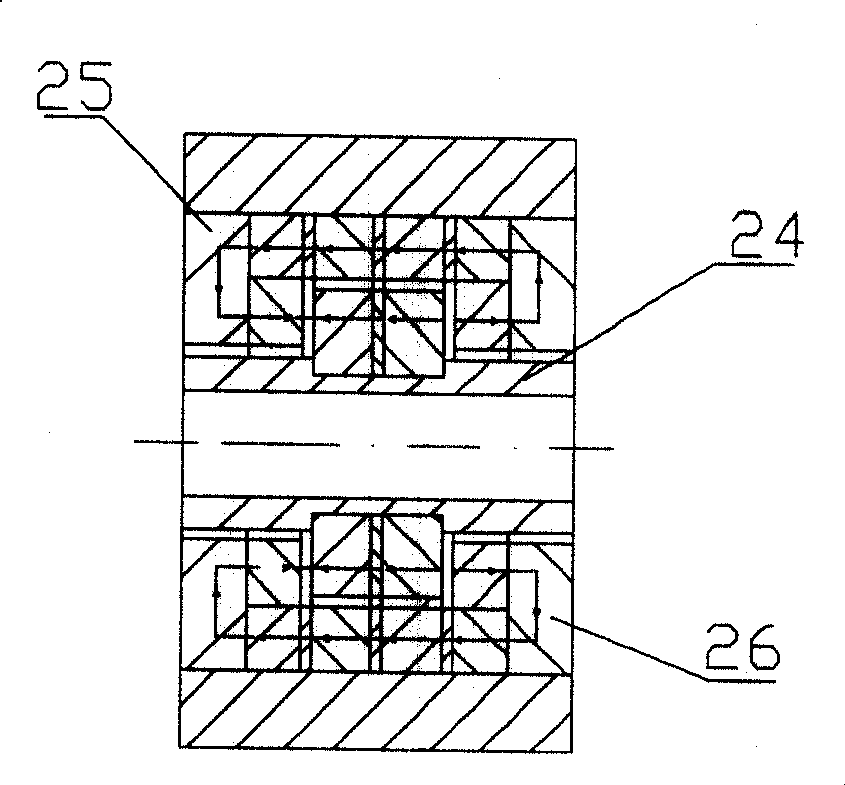
[0039] Implementation mode 3: if image 3 Show. If the rotational speed of the supported rotating shaft is low, the jumping and swinging are very small, or in a vacuum environment, then the bearing described in Embodiment 1 or 2 does not need to be equipped with a turbine, and becomes a pure permanent magnetic suspension bearing. The non-magnetic rotary sleeve 7, the magnetic conduction disk 5 and 14 in Embodiment 1 are correspondingly changed into image 3 Shown non-magnetic rotary sleeve 24, magnetic conduction disk 25 and 26.


PUM


Abstract

The present invention discloses a permanent magnet and composite turbine bearings to resolve the existing magnetic bearings complex structures with small unit volume capacity, poor stability operations, the application of limitations and other issues. The invention is made of a internal sleeve and external one which is equipped with axial ring-shape Permanent-Magnet, the internal and external sleevee of PM have a clearance that belongs to homopolarity , thus the internal and external sleeve relatively float each other. The two end fo said sleeve is equipped with a turbine, when they rotate with high speed, the turbine presss the liquid into clearance between internal and external sleeve to form high-pressure cushion or static seal, extremely prevents the two sleeve from ralatively flopping and swinging, thus improves the stable operation of bearing and reliability. The invention is cramped construction, high rigid, high bearing capacity of unit volume, stable operation and widely application.

Description

technical field [0001] The invention relates to a magnetic suspension bearing, in particular to a permanent magnet and turbine composite bearing. Background technique [0002] The rotating sleeve and the fixed sleeve of the magnetic suspension bearing are relatively suspended by magnetic force, so there is no friction, no noise, no pollution, no vibration transmission, no lubrication, no maintenance, and long service life during operation. [0003] Magnetic suspension bearings include electromagnetic type, permanent magnet type, electromagnetic permanent magnet combined type, permanent magnet and high temperature superconductor composite type. The electromagnetic type uses the magnetic force generated by the current to make the inner sleeve and outer sleeve of the bearing relatively suspended. The structure of the electromagnetic magnetic suspension bearing is complex, and a complex circuit control system needs to be configured to make the inner sleeve operate with satisfac...

Claims


Application Information

Patent Timeline
Patent Type & Authority Patents(China)
IPC IPC(8): F16C32/00F16C32/04
Inventor 刘新广
Owner 刘新广
Why Eureka
Try Eureka