Optical fibre grating sensor based on Bourdon tube as energy changer and method thereof

A fiber grating and sensor technology, applied in the field of sensors, can solve the problems of increased failure rate of strain gauges and electrical signal amplification systems, inability to realize real-time separation and detection of pressure and temperature, immature processing technology and modular design, etc., to improve Environmental adaptability and application fields, high reliability, simple modular effect

Inactive Publication Date: 2009-02-11
INST OF SEMICONDUCTORS - CHINESE ACAD OF SCI
View PDF7 Cites 0 Cited by
  • Summary
  • Abstract
  • Description
  • Claims
  • Application Information

AI Technical Summary

Problems solved by technology

[0005] The existing Bourdon tube test pressure technology is to paste the resistance strain gauge on the place with the largest strain on the Bourdon tube. The resistance strain gauge used in it is easy to cause signal drift under the temperature change or electromagnetic field interference, and the increase of temperature will make the strain The failure rate of the amplifying system of chips and electric signals is greatly increased, such as (PRC Utility Model Patent Application Specification CN85 2 03516 U)
The existing fiber grating pressure and temperature sensors are rare, and the processing technology and modular design are immature, the structure is complex, and the sealing is difficult. For example, Tsinghua University once proposed to use a circular pressure transducer combined with a cantilever beam. Institution (Invention Patent Application Specification of the People's Republic of China, Application No. 02121327.5, Publication No. CN1384341A)
However, the existing Bourdon tube fiber grating pressure sensor does not use a double grating structure, which cannot realize the real-time separation and detection of pressure and temperature, and the material used in the cantilever beam is polymer such as plexiglass. No matter in the temperature measurement range, stability, There are big problems in terms of repeatability and reliability, and it cannot be practical

Method used


Image

  • Optical fibre grating sensor based on Bourdon tube as energy changer and method thereof
  • Optical fibre grating sensor based on Bourdon tube as energy changer and method thereof
  • Optical fibre grating sensor based on Bourdon tube as energy changer and method thereof

Examples


Embodiment Construction

[0019] The present invention will be described in further detail below in conjunction with the accompanying drawings.

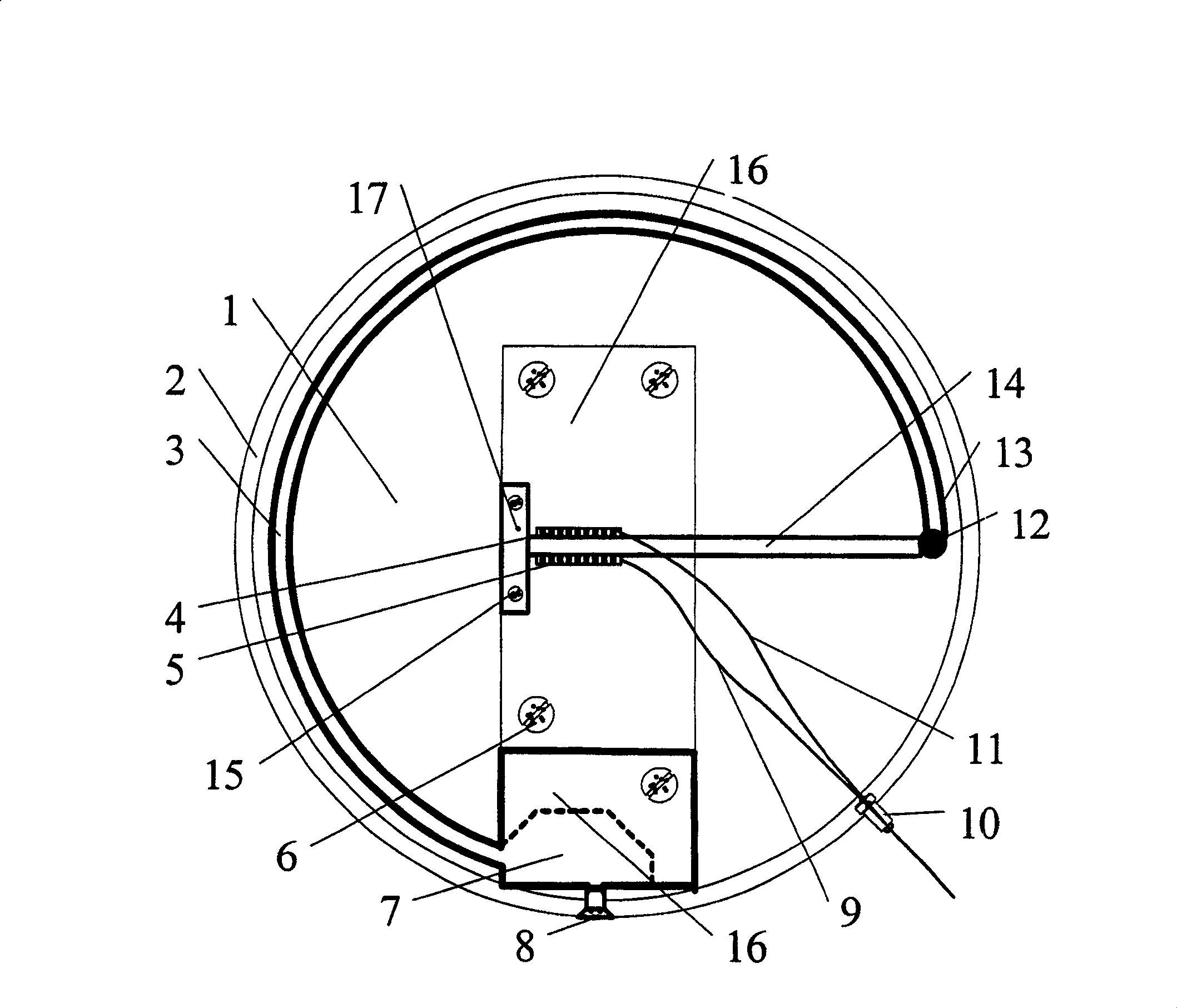
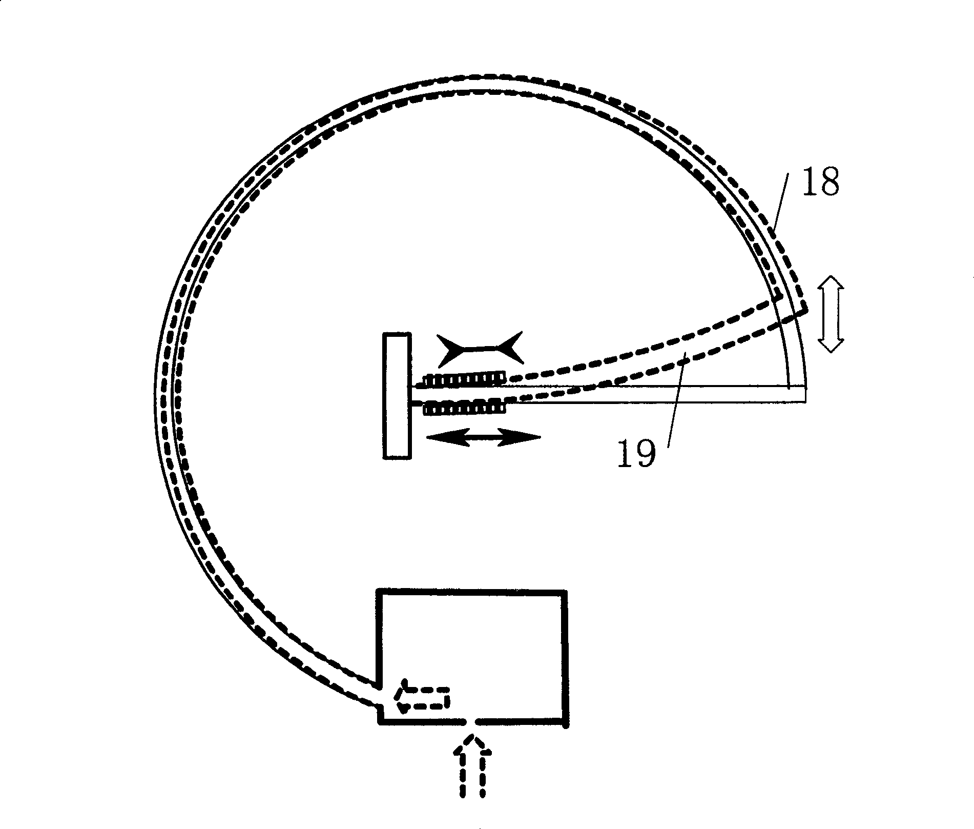
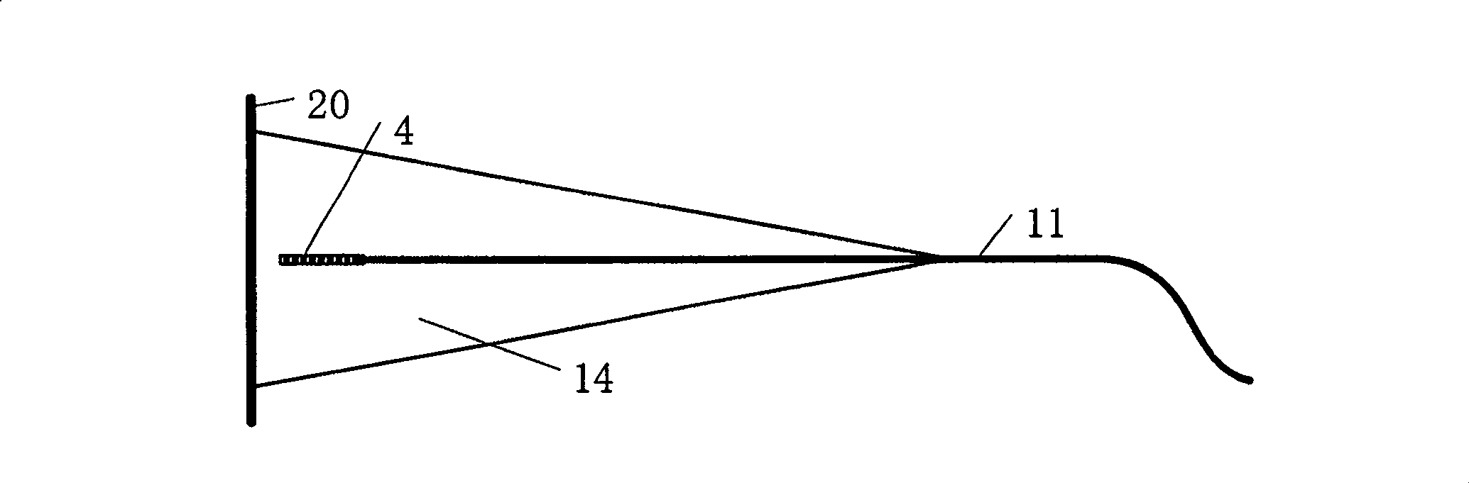
[0020] figure 1 It is a structural schematic diagram of the fiber grating sensor of the present invention. The sensor mainly includes a Bourdon tube (also called spring tube) pressure transducer 3, and the transducer (ie Bourdon tube) 3 includes a first installation base 16 containing a pressure guide hole 7 and a closed free end 13, The first installation base 16 is fixed on the lower base plate 1 by several screws 6, the free end 13 is fixed on the point 12 with the fiber grating cantilever beam 14 by welding or bonding, and the pressure guide nozzle 8 is connected with the pressure guide hole 7 , to guide the external pressure into the Bourdon tube 3; the fiber grating cantilever beam 14 is fixed on the second installation base 17 by fastening screws 15, and the two fiber gratings 4 and 5 with the same performance and with pigtails 9 and 11 They are past...


PUM


Abstract

The invention relates to optical fiber grating sensor and method based on bourdon tube used as transducer. It includes one bourdon tube pressure transducer, one optical fiber grating cantilever, optical fiber coupler, transmitting optical fiber, package shell, fastening location device, sealing device. The bourdon tube makes its cross section incline to circular under the action of inner pressure, compel free end 13 to make a move which is sent to cantilever 14 to make it flexural strain by connecting point 13. The optical fiber grating 4, 5 pasted under the cantilever 14 are respectively suffered the tension strain or compressive strain epsilon to make optical fiber grating Bragg wave length drift. The tested pressure and temperature can be known by testing the wave length change of the two optical grating.

Description

technical field [0001] The invention relates to the technical field of sensors, in particular to a fiber grating sensor and a method based on a Bourdon tube (also called a spring tube) as a pressure transducer. Background technique [0002] The measurement of pressure and temperature has long been a very important parameter in the modern industrial production process. In petrochemical industry, exploration and production of oil and gas fields, aviation instruments, underwater operations and other fields, electrical quantity sensors are generally used to measure pressure and temperature separately, and then the signals are transmitted to the terminal through cables for signal processing. Due to the poor adaptability of electronic components to harsh environments (every 10°C increase in temperature will double the failure rate of electronic instruments), weak electrical signals are prone to electromagnetic interference (inherently deficient in electromagnetic measurement), spe...

Claims


Application Information

Patent Timeline
Patent Type & Authority Patents(China)
IPC IPC(8): G01D5/26G01D5/353
Inventor 王永杰李芳刘育梁
Owner INST OF SEMICONDUCTORS - CHINESE ACAD OF SCI
Why Eureka
Try Eureka