Combined type flow guide polar plate suitable for normal pressure or low pressure fuel cell

A fuel cell and bipolar plate technology, applied to fuel cell components, fuel cells, battery electrodes, etc., can solve problems such as reduced safety, negative values, electrode breakdown, etc., to reduce flow resistance and flow resistance Large, not easy to block the effect of water

Active Publication Date: 2009-02-25
SHANGHAI MUNICIPAL ELECTRIC POWER CO +1
View PDF7 Cites 0 Cited by
  • Summary
  • Abstract
  • Description
  • Claims
  • Application Information

AI Technical Summary

Problems solved by technology

[0015] In addition, in order to prevent the water generated by the fuel cell from clogging the diversion groove, it is often used to increase the metering ratio of air and hydrogen in the operation of the fuel cell, that is, to increase the flow rate of air and hydrogen, and use excess air and hydrogen to take the product water out of the fuel cell. This operation method actually increases the operating pressure of the fuel cell, increases the operating cost, reduces the safety, and is contrary to the design of the fuel cell to be suitable for normal pressure or low pressure operation (especially when used as a vehicle or ship engine) At the same time, the efficiency of the fuel cell system is greatly reduced, because the excess air is wasted or the excess hydrogen is circulated, which will inevitably increase the mechanical power consumption of conveying air or circulating hydrogen, thereby reducing the efficiency of the fuel cell system
[0016] Thirdly, when the air flow groove or the hydrogen flow groove of the fuel cell deflector plate is blocked during operation, some blockages will appear. The battery voltage is very low or even negative, resulting in unstable operation of the fuel cell, and in severe cases, the electrodes will be broken down. , and destroy the entire stack

Method used


Image

  • Combined type flow guide polar plate suitable for normal pressure or low pressure fuel cell
  • Combined type flow guide polar plate suitable for normal pressure or low pressure fuel cell
  • Combined type flow guide polar plate suitable for normal pressure or low pressure fuel cell

Examples


Embodiment 1

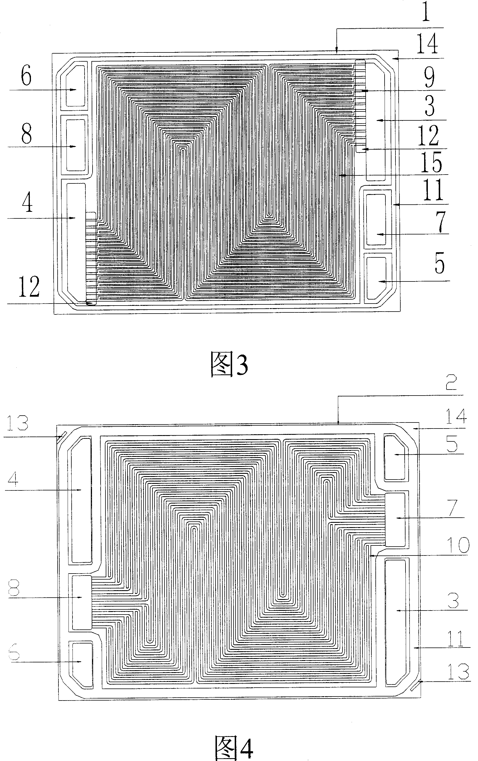
[0040] Such as figure 2 ,Figure 4, Figure 5 As shown, the combined flow guide bipolar plate suitable for atmospheric pressure fuel cells has a size of 150×200×1.5mm. The flow guide bipolar plate is that the air guide plate 1 is opposite to the cooling fluid plate 2 and guides the flow of hydrogen The plate 16 is a rectangular flow-guiding bipolar plate that is integrated, and the flow-guiding bipolar plate includes an air inlet main hole 3, an air outlet main hole 4, a hydrogen inlet main hole 5, a hydrogen outlet main hole 6, and a cooling fluid inlet main hole 7. Cooling fluid outlet mainstream holes 8, each fluid inlet and outlet mainstream holes are arranged at the two ends of the rectangular diversion bipolar plate, the air inlet and outlet mainstream holes of the air deflector 1 are provided with a plurality of air Launder 9, a plurality of cooling fluid launders 10 are arranged between the cooling fluid inlet and outlet main holes of the cooling fluid plate 2, and a ...

Embodiment 2

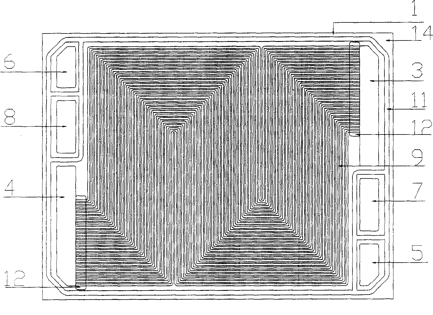
[0050] Figure 3, Figure 4, Figure 5 As shown, the combined flow guide bipolar plate suitable for atmospheric pressure fuel cells has a size of 150×200×1.5mm. The flow guide bipolar plate is that the air guide plate 1 is opposite to the cooling fluid plate 2 and guides the flow of hydrogen The plate 16 is a rectangular flow-guiding bipolar plate that is integrated, and the flow-guiding bipolar plate includes an air inlet main hole 3, an air outlet main hole 4, a hydrogen inlet main hole 5, a hydrogen outlet main hole 6, and a cooling fluid inlet main hole 7. Cooling fluid outlet mainstream holes 8, each fluid inlet and outlet mainstream holes are arranged at the two ends of the rectangular diversion bipolar plate, the air inlet and outlet mainstream holes of the air deflector 1 are provided with a plurality of air Launder 9, a plurality of cooling fluid launders 10 are arranged between the cooling fluid inlet and outlet main holes of the cooling fluid plate 2, and a plurality ...

Embodiment 3

[0055] What is used in the fuel cell stack in Example 1 is a fuel cell air deflector plate suitable for normal-pressure air operation, with a size of 150×200×1.5mm. This embodiment 3 is a kind of fuel cell that is suitable for low-pressure air operation. The fuel cell air guide plate has a size of 150×200×1.5mm, and other designs are the same as those in Example 1, the difference is: air flow groove depth×groove width=0.3×0.8mm, the main flow groove is the same as the branch flow The number of grooves is 20, and the flow resistance encountered by air entering from the inlet of the guide plate is larger than that in Example 1, so the operating pressure of the air is about 0.5 atmospheric pressure (relative pressure), and other cooling fluid guide fields The structure of the hydrogen diversion field is the same as in Example 1.


PUM


Abstract

The invention discloses a fuel battery air diversion bipolar plate in the normal pressure or lower pressure condition, which is characterized by the following: the air diversion bipolar plate is square diversion bipolar board of integral bifarious combination of air diversion board and cooling water board, which contains air inlet main stream hole, air outlet main stream hole, hydrogen inlet main stream hole, hydrogen outlet main stream hole, cooling water inlet main stream hole, cooling water outlet main stream hole with diagonal distribution for each inlet and outlet hole, wherein several cooling water diversion grooves are set between cooling water board inlet and outlet main stream holes; several hydrogen diversion grooves are set between hydrogen diversion inlet and outlet main stream holes. The invention is not easy to block diversion groove, which operates stably.

Description

technical field [0001] The invention relates to a fuel cell, in particular to a combined flow guide bipolar plate suitable for normal pressure or low pressure fuel cells. Background technique [0002] An electrochemical fuel cell is a device that converts hydrogen fuel and oxidant into electrical energy and reaction products. The internal core component of the device is the membrane electrode (Membrane Electrode Assembly, referred to as MEA). The membrane electrode (MEA) is composed of a proton exchange membrane and two porous conductive materials, such as carbon paper, sandwiched between the two sides of the membrane. On the two boundary surfaces of the membrane and the carbon paper, there are even and finely dispersed catalysts for initiating electrochemical reactions, such as metal platinum catalysts. Conductive objects can be used on both sides of the membrane electrode to draw the electrons generated during the electrochemical reaction through an external circuit to fo...

Claims


Application Information

Patent Timeline
Patent Type & Authority Patents(China)
IPC IPC(8): H01M4/86H01M8/02H01M8/0258H01M8/026
CPCY02E60/50
Inventor 夏建伟胡里清
Owner SHANGHAI MUNICIPAL ELECTRIC POWER CO
Why Eureka
Try Eureka