

Air cleaner
A technology of air purification device and discharge device, which is applied in air quality improvement, air conditioning system, gas treatment, etc., can solve problems such as energy waste, and achieve the effects of reducing generation amount, suppressing discharge power waste, and improving energy saving.
- Summary
- Abstract
- Description
- Claims
- Application Information
AI Technical Summary
Problems solved by technology
Method used
Image

Examples
Embodiment approach 1
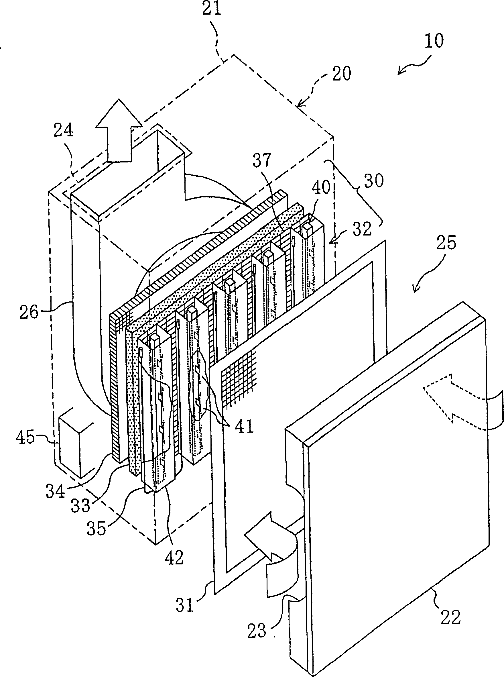
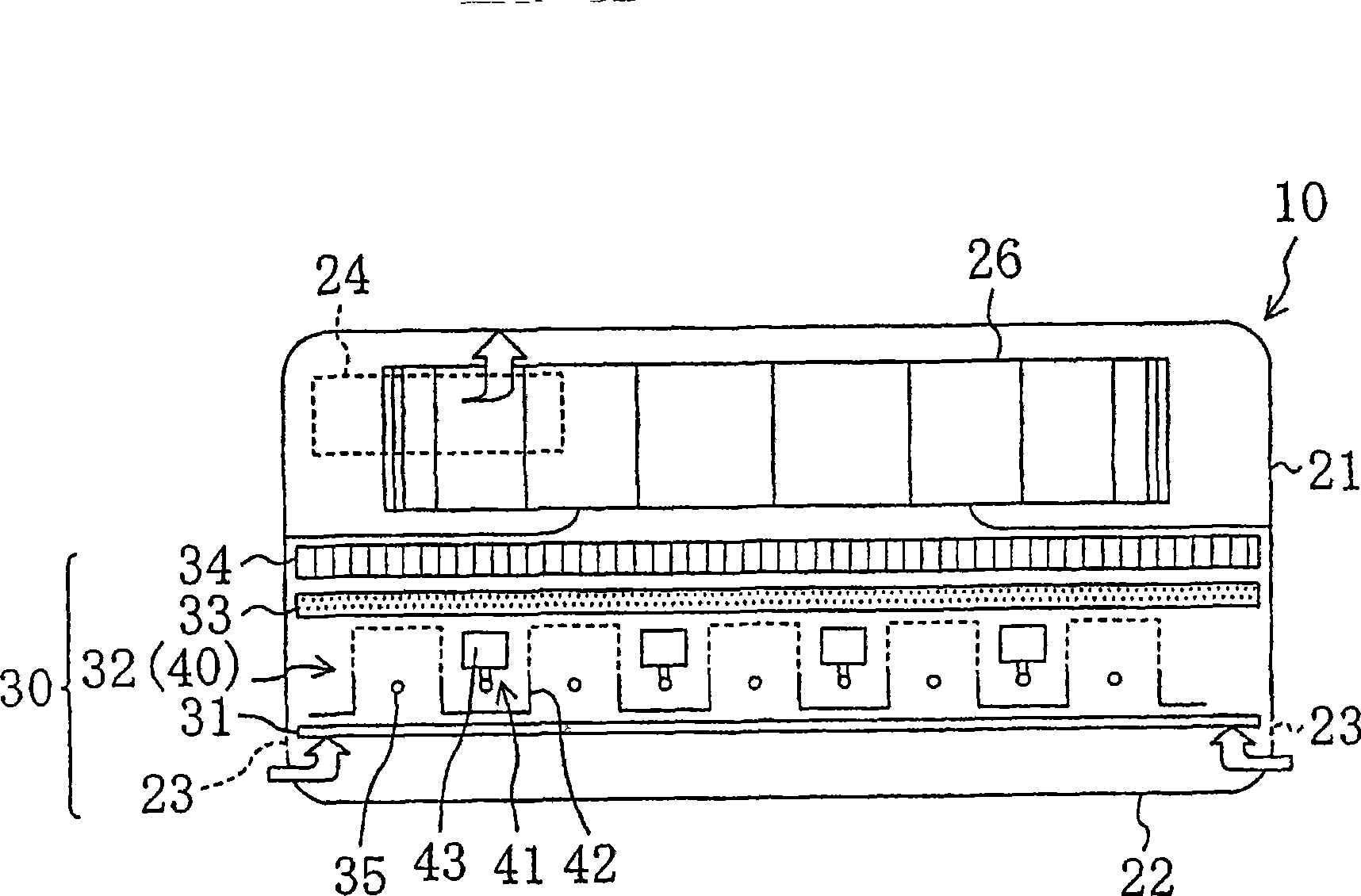
[0059] First, refer to figure 1 The air cleaning device (10) according to Embodiment 1 will be described through FIG. 4 .
[0060] figure 1 It is an exploded perspective view of the air cleaning device (10) of Embodiment 1, figure 2 It is the figure which looked at the inside of this air cleaning device (10) from above. The air cleaning device (10) is a civilian air cleaning device used in ordinary households, small-scale stores and the like. In addition, the air purifier (10) is an air purifier of a so-called streamer discharge method in which low-temperature plasma is generated by streamer discharge to purify air to be treated.
[0061] The air cleaning device (10) has a casing (20) composed of a box-shaped casing main body (21) with one end open and a front panel (22) attached to the open end surface. Suction ports (23) are formed on both side surfaces of the casing (20) on the front panel (22) side. In addition, an air outlet (24) is formed in the case main body (2...
Embodiment approach 2
[0110] Next, an air cleaning device (10) according to Embodiment 2 will be described with reference to FIG. 9 . The structure of the power supply unit (45) of the air cleaner (10) of Embodiment 2 differs from Embodiment 1, and the structure other than that is the same structure as Embodiment 1. Hereinafter, only differences from Embodiment 1 will be described.
[0111] As shown in FIG. 9 , two high voltage power supply units including a first high voltage power supply unit ( 71 ) and a second high voltage power supply unit ( 72 ) are provided in the power supply unit ( 45 ) of the second embodiment. The two high-voltage power supply units (71, 72) have different specifications, and are configured to output different power (current) to the discharge device (40). Specifically, the first high-voltage power supply unit (71) is configured to output streamer discharge power to the discharge device (40) at a discharge current (first set discharge power) of 37 μA in the discharge dev...
Embodiment approach 3
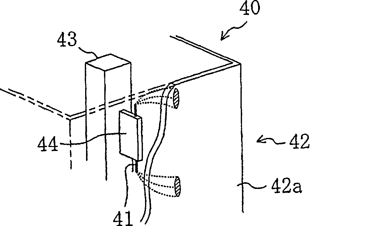
[0123] Next, an air cleaning device (10) according to Embodiment 3 will be described with reference to FIG. 10 . The plurality of discharge electrodes (41) of the air cleaning device (10) of Embodiment 3 and the opposite electrode (42) facing each discharge electrode (41) are modularized into two discharge devices (the first discharge device (40a ) and the second discharge device (40b)). Then, a first high-voltage power supply part (40a) corresponding to the first discharge device (40a), and a second high-voltage power supply part (40b) corresponding to the second discharge device (40b) are provided. In addition, the first high-voltage power supply unit (40a) and the second high-voltage power supply unit (40b) each have the same specifications, and are configured to output the power of streamer discharge at a discharge current of 37 μA in the corresponding discharge device to each discharge device. . In addition, an on / off control unit (63b) capable of individually on / off co...
PUM
 Abstract
Description
Claims
Application Information