Strong coupling multiple core optical fiber

A multi-core fiber, strong coupling technology, applied in the direction of multi-core/clad fiber, clad fiber, optical waveguide light guide, etc., can solve the problem that multi-core fiber is not easy to achieve strong coupling

Inactive Publication Date: 2009-06-03
SHANGHAI INST OF OPTICS & FINE MECHANICS CHINESE ACAD OF SCI
View PDF4 Cites 1 Cited by
  • Summary
  • Abstract
  • Description
  • Claims
  • Application Information

AI Technical Summary

Problems solved by technology

[0007] The purpose of the present invention is to overcome the disadvantage that multi-core optical fiber is not easy to achieve strong coupling, and provide a strong coupling multi-core optical fiber

Method used


Image

  • Strong coupling multiple core optical fiber
  • Strong coupling multiple core optical fiber
  • Strong coupling multiple core optical fiber

Examples


Embodiment 1

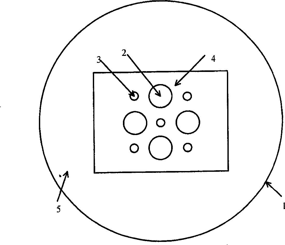
[0024] figure 1 In order to invent the schematic diagram of the fiber cross-section of Embodiment 1 of the strongly coupled multi-core fiber, it can be seen from the figure that the large-diameter cores 2 in the inner cladding region 4 are arranged in a square, and the sub-wavelength diameter cores 3 are located in four large cores. A strongly coupled multi-core fiber between two diameter cores. This strongly coupled multi-core fiber is made by embedding a large-diameter core 2 and a sub-wavelength diameter core 3 in the inner cladding region 4 , and covering the outer cladding region 5 on the inner cladding region 4 . The core diameter of the large-diameter core 2 is 3 μm, the core diameter of the sub-wavelength diameter core 3 is 100 nm, the shape of the inner cladding region 4 is rectangular, the size is 60 μm×40 μm, and the diameter of the outer cladding is 125 μm. The refractive index of the large core diameter 2 and the sub-wavelength diameter core 3 are both 1.458, the...

Embodiment 2

[0026] The difference between embodiment 2 and embodiment 1 is that the sub-wavelength diameter core 3 is not doped, and the large core diameter core 2 is phosphate glass doped with 2wt% ytterbium oxide, and doped with aluminum ions to improve performance.

Embodiment 3

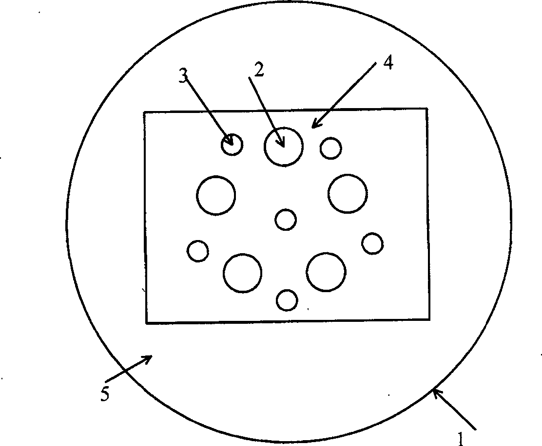
[0028] figure 2 It is a schematic cross-sectional view of an optical fiber in Embodiment 3 of the present invention. This is a strongly coupled multi-core fiber in which the large-diameter cores 2 in the inner cladding region 4 are arranged in a pentagon, and the sub-wavelength diameter core 3 is located among the five large-diameter cores 2 . This strongly coupled multi-core fiber is made by embedding a large-diameter core 2 and a sub-wavelength diameter core 3 in the inner cladding region 4 , and covering the outer cladding region 5 on the inner cladding region 4 . The diameter of the large-diameter core 2 is 3 μm, the sub-wavelength diameter core 3 is 100 nm, the shape of the inner cladding region 4 is rectangular, and the size is 60 μm×40 μm, and the diameter of the outer cladding region 5 is 125 μm. The refractive index of the large core diameter 2 and the sub-wavelength diameter core 3 are both 1.458, the refractive index of the inner cladding region 4 is 1.45, and the...


PUM


Abstract

A strong coupling multi-core optical fiber includes a core area, an internal cladding area and an external cladding area. The optical fiber is characterized in that the core area includes a plurality of large cores and a plurality of sub-wavelength cores arranged in the internal cladding area; the refractive index of the internal cladding area is smaller than that of the large core and the sub-wavelength core but larger than that of the external cladding area; the internal and external cladding areas are both made of solid material with evenly distributed refractive index; the diameter of the large core is in micron dimension, the distance between adjacent large cores is in micron dimension and the diameter of the sub-wavelength core is in hundred micron dimension. The invention has the functions of strong coupling, phase locking, laser shaping and homogenization.

Description

technical field [0001] The invention relates to an optical fiber, especially a strongly coupled multi-core optical fiber. Background technique [0002] High-power fiber lasers have been increasingly widely used in laser processing, laser medical treatment, laser radar, laser ranging and many other aspects due to their excellent performance and value-for-money price. Under the same output power, fiber lasers have advantages in beam quality, reliability, and size. In addition, due to the reduction of fiber costs and the ease of mass production in assembly lines, this not only arouses the interest of scientists, but also attracts more attention. The great concern of industry experts. [0003] Fiber lasers were first proposed in the 1960s, but progress has been slow until the development and application of low-loss fiber manufacturing technology and semiconductor lasers brought new prospects for fiber lasers. Fiber lasers use doped fibers as the laser medium. Compared with bul...

Claims


Application Information

Patent Timeline
Patent Type & Authority Patents(China)
IPC IPC(8): G02B6/036G02B6/02
Inventor 赵楚军范滇元唐志祥钱列加
Owner SHANGHAI INST OF OPTICS & FINE MECHANICS CHINESE ACAD OF SCI
Why Eureka
Try Eureka