Superstructure of engine

A technology of engine and structure, applied in the direction of engine starting, engine cooling, engine components, etc., can solve the problems of damaged connecting rod, oil hammer, increased cost, etc., and achieve the effect of simple assembly, prevention of assembly errors, and rapid assembly

Inactive Publication Date: 2009-07-15
YANMAR CO LTD
View PDF12 Cites 0 Cited by
  • Summary
  • Abstract
  • Description
  • Claims
  • Application Information

AI Technical Summary

Problems solved by technology

As a result, excess oil enters the combustion chamber and, as a result, there is a risk of oil hammer and damage to the connecting rod, etc.
And when the injection path of the starting aid is additionally set, the cost will be increased

Method used


Image

  • Superstructure of engine
  • Superstructure of engine
  • Superstructure of engine

Examples


Embodiment Construction

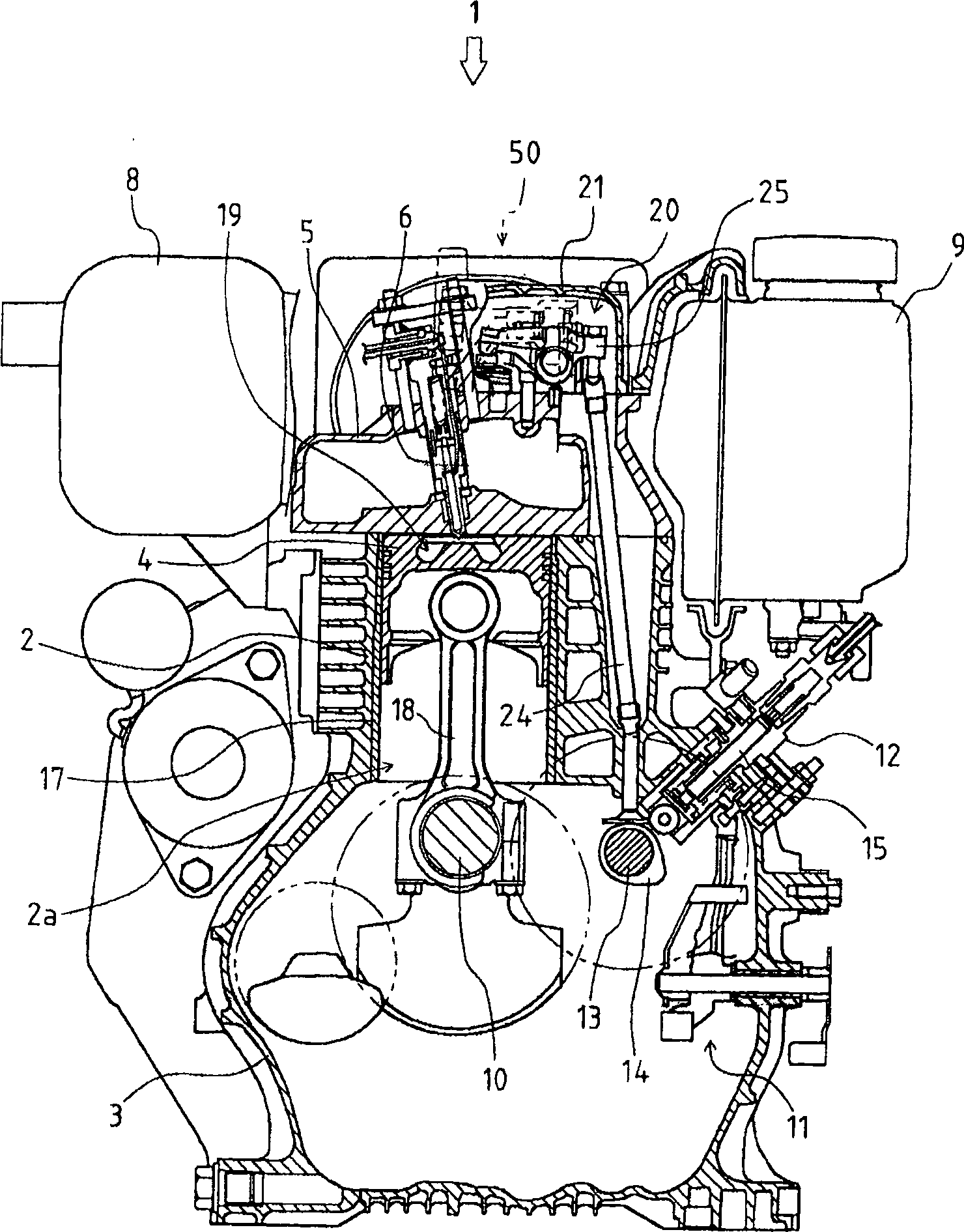
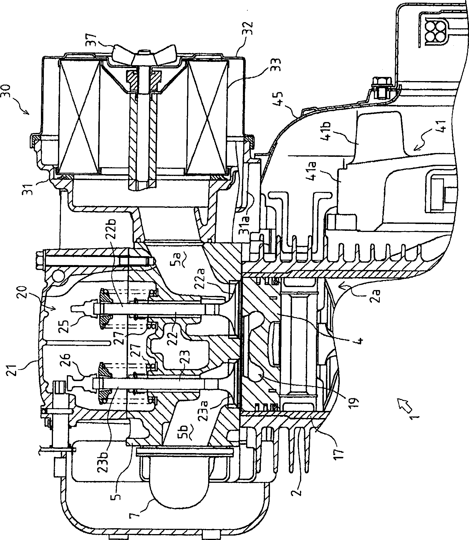
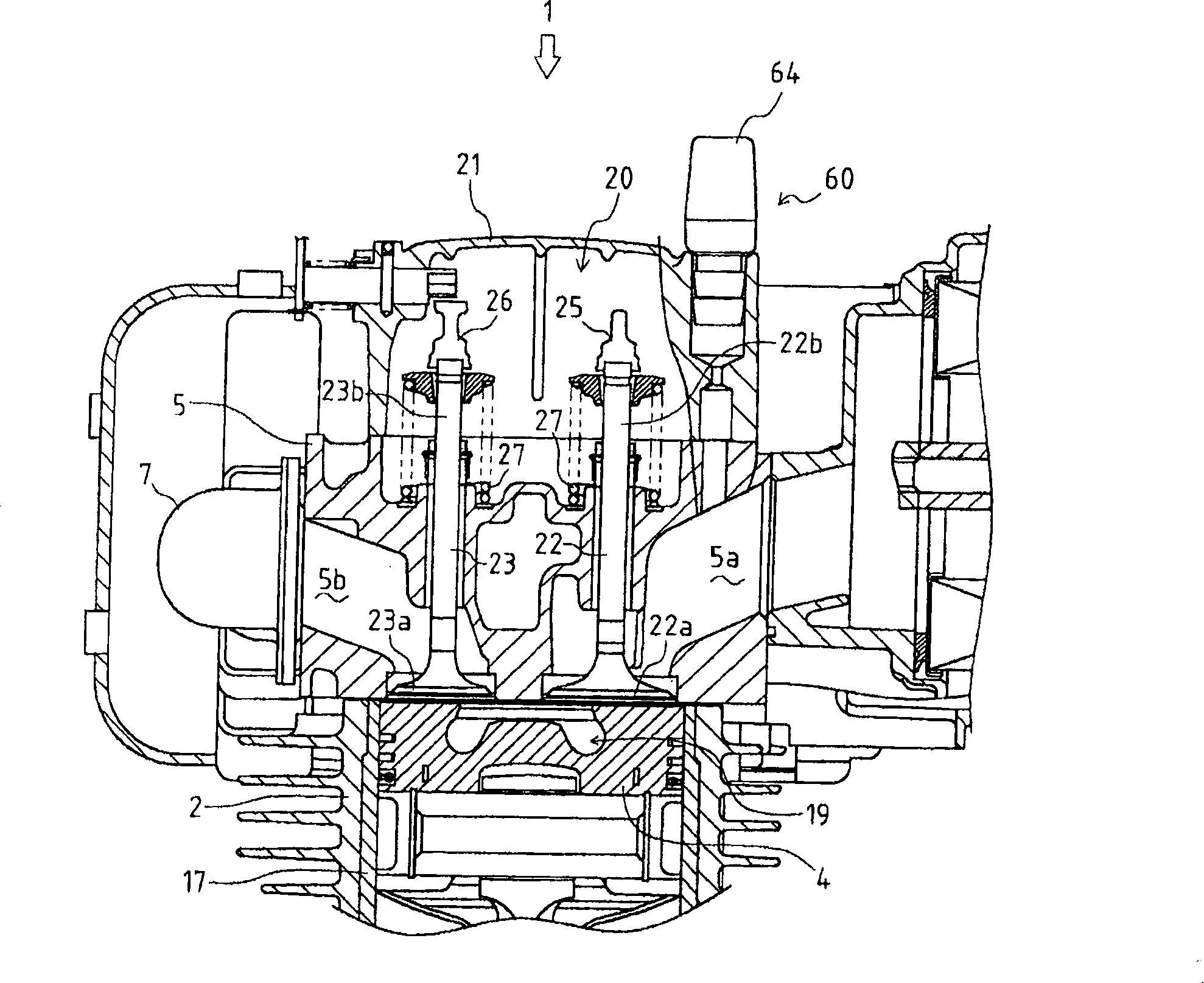
[0046] First, use Figure 1 to Figure 3 The overall structure of the engine 1 of the present invention will be described.

[0047] The engine 1 consists of a cylinder block 2 constituting the upper part of its main body, and a crankcase 3 constituting the lower part of its main body. The cylinder block 2 forms a cylinder 2a in the vertical direction at the center thereof, and accommodates the piston 4 in a cylinder liner 17 inside the cylinder 2a so as to be slidable in the vertical direction. Below the cylinder block 2 , a crankshaft 10 is pivotally supported by the crankcase 3 in the front-rear direction, and the crankshaft 10 and the piston 4 are connected by a connecting rod 18 .

[0048] The upper portion of the aforementioned cylinder block 2 is covered by a cylinder head 5 . In this cylinder head 5, an intake valve 22, an exhaust valve 23, a fuel injection nozzle 6, and the like are arranged. The upper side of the cylinder head 5 is covered by a valve arm case 21 to ...


PUM


Abstract

PROBLEM TO BE SOLVED: To provide an engine upper structure capable of preventing exhaust emission, oil hammer or the like by devising a shape of a baffle plate provided on a vent hole (an inlet) of a breather provided on an upper part of a valve arm chamber of an engine, and a shape of an engine starting aid filling passage of, and disposing the breather and the engine starting aid filling passage in a compact and collective manner. SOLUTION: A slit 34 with a lower portion thereof opened is formed in a baffle plate 33 formed around a vent hole 36 of a breather 30, a throttle 45 is formed in a filling passage 42 of an engine starting aid, and the breather 30 and the filling passage 42 are integrated with a valve arm case 21. COPYRIGHT: (C)2004,JPO&NCIPI

Description

technical field [0001] The present invention relates to the upper structure of the engine, in particular, to the structure of the air cleaner for cleaning the air supplied to the combustion chamber of the engine, the structure of the breather device arranged on the upper part of the valve arm chamber, and the structure of the air cleaner And the construction of the suction part of the breather to the cylinder head. Background technique [0002] In the past, in the engine, an air cleaner for purifying the air supplied to the combustion chamber was installed on the upper part of the engine, and the outside air was introduced and purified by the air cleaner, and the cleaned outside air was used as a combustion engine. Air is supplied to the combustion chamber. [0003] In this air cleaner, an air intake portion is provided on a cover as a constituent member of the air cleaner, and external air is directly sucked into the air filter from the air intake portion, or, for example,...

Claims


Application Information

Patent Timeline
Patent Type & Authority Patents(China)
IPC IPC(8): F02M35/024F01M13/02F01P5/06F02M25/06F01M13/00F01M13/04F02F1/42F02N19/00
CPCY02T10/146
Inventor 佐茂纯一盐田克之金津康弘西村伸治相良昌史
Owner YANMAR CO LTD
Why Eureka
Try Eureka