Automatic clutch for motorcycle

A technology for automatic clutches and vehicles. It is applied in automatic clutches, clutches, mechanical drive clutches, etc., and can solve the problems of low transmission efficiency and poor automatic performance.

Inactive Publication Date: 2009-07-22
江大建 +1
View PDF4 Cites 0 Cited by
  • Summary
  • Abstract
  • Description
  • Claims
  • Application Information

AI Technical Summary

Problems solved by technology

[0005] The invention provides an automatic clutch for vehicles, which can effectively solve the problems of poor automatic performance and low transmission efficiency of existing vehicle clutches

Method used


Image

  • Automatic clutch for motorcycle
  • Automatic clutch for motorcycle
  • Automatic clutch for motorcycle

Examples


Embodiment 1

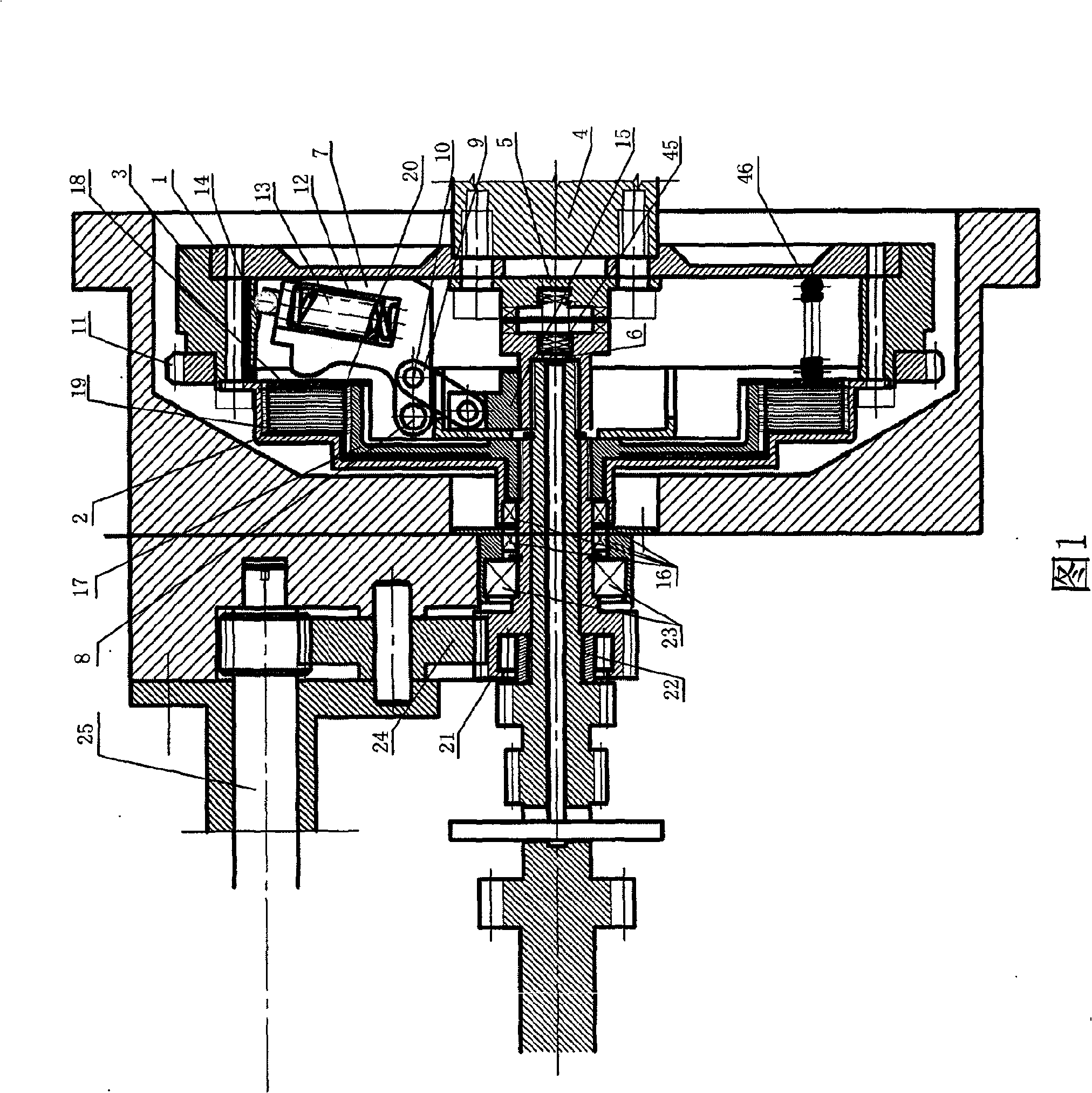
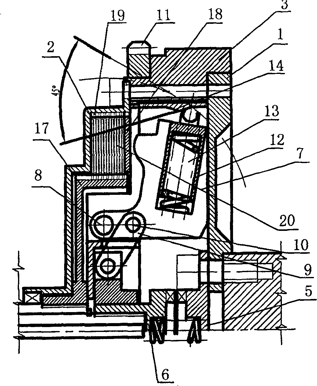
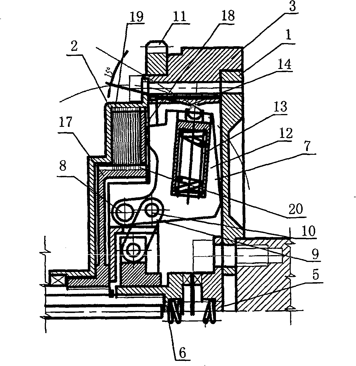
[0034] As shown in Figures 1 to 8, an automatic clutch for a vehicle includes a front disc, a rear disc and a middle disc. The front disc is a circular metal disc, and the right end of the center part of the front disc is coaxially fixed with the output shaft of the engine. The left end of the central part is coaxially connected to a fixed gear pair of an end-face toothed locker. The movable gear pair is coupled with the fixed gear pair. The movable gear pair is installed on the input shaft of the gearbox in a splined manner. The fixed gear pair A separation spring between the pair and the movable tooth pair keeps the locker in a constant state; the middle plate is a circular metal plate, and the left end of the outer circle is coaxially fixed with the rear plate; the rear plate is a circular metal plate Disk, the outer circle of the rear disk is fixedly connected with the central disk, the center of the left end of the central disk is wall-shaped, forming a cavity with the wal...

Embodiment 2

[0050] An automatic clutch for a vehicle, comprising a front disc, a rear disc and a middle disc, the front disc is a circular metal disc, the right end of the central part of the front disc is coaxially connected with the output shaft of the engine, and the left end of the central part is coaxially connected to the A fixed gear pair of an end-toothed locking device is coupled with a movable gear pair. The movable gear pair is installed on the input shaft of the gearbox in a spline manner. Only the separation spring keeps the locker in a normal state; the middle plate is a circular metal plate, the right end of the outer circle of the middle plate is coaxially fixed with the front plate, and the left end of the outer circle is coaxially fixed with the rear plate; the rear plate It is a circular metal plate, and the right end of the outer circle of the rear plate is fixedly connected with the middle plate. The center part of the left end of the middle plate is wall-shaped, formi...

Embodiment 3

[0066] An automatic clutch for a vehicle, comprising a front disc, a rear disc and a middle disc, the front disc is a circular metal disc, the right end of the central part of the front disc is coaxially connected with the output shaft of the engine, and the left end of the central part is coaxially connected to the A fixed gear pair of an end-toothed locking device is coupled with a movable gear pair. The movable gear pair is installed on the input shaft of the gearbox in a spline manner. Only the separation spring keeps the locker in a normal state; the middle plate is a circular metal plate, the right end of the outer circle of the middle plate is coaxially fixed with the front plate, and the left end of the outer circle is coaxially fixed with the rear plate; the rear plate It is a circular metal plate, and the right end of the outer circle of the rear plate is fixedly connected with the middle plate. The center part of the left end of the middle plate is wall-shaped, formi...


PUM


Abstract

The invention discloses an automatic coupler for vehicles, which comprises a front tray, a back tray, and a middle tray. The invention is characterized in that the central part of the left end of the middle tray is in wall shape and forms a cavity together with the wall of the back tray to restrict the axial displacement of a driven tray shaft arranged at the left side. An abdominal cavity of the middle tray is coaxially and uniformly hinged with 2 to 6 fly hammers which bear and transmit power. A hammer handle is arranged at the left part of the fly ball and a hammer body is arranged at the right part. The left end of the handle is provided with a pivoting hole which is hinged on the hinge base at the middle part of the left side of the middle tray. The right side of the hammer handle is also provided with a hole hinged with a connecting rod. The left side of the right part hammer body is provided with a pressing finger pressed at the right end of a clutch pressure plate. A cavity of the hammer body in the right part is provided with an offset piston and an offset piston spring. The spherical top end of the offset piston reciprocates on an orbit on a cavity wall of an inner hole of the middle tray. The high-speed centrifugal force of an engine leads a fly hammer group to be pressed and arranged in a clutch membrane group in the back tray and transmits power to an output tray connected with a gearbox. The invention has the advantages of simple structure, god self-moving responsiveness, regular joint, high transmission efficiency, long service life and proper cost.

Description

technical field [0001] The invention relates to the field of motor vehicle transmission, in particular to a vehicle automatic clutch. Background technique [0002] In the power transmission chain of motor vehicles (such as automobiles, trains, tractors, engineering vehicles, tanks, armored vehicles, motorcycles, etc.), an important transmission component is the clutch. The clutch plays the role of transmitting and cutting off the power. Different from the general machine clutch, the motor vehicle clutch needs to meet the needs of the motor vehicle to engage and cut off the power under various working conditions. Its performance is much higher, especially for automatic transmission motor vehicles. Higher and more demanding clutch performance requirements. [0003] The existing motor vehicle clutch mainly adopts two types, one is a hydraulic torque converter (hydraulic coupling), which is mainly used in automatic transmission vehicles, continuously variable transmission vehic...

Claims


Application Information

Patent Timeline
Patent Type & Authority Patents(China)
IPC IPC(8): F16D43/10F16D13/70F16D69/02
CPCF16D43/10
Inventor 江大建谢纯茂
Owner 江大建
Why Eureka
Try Eureka