Solution dehumidification evaporation and cooling air conditioner device capable of utilizing indoor exhaust air cool and heat
An evaporative cooling air conditioner and solution dehumidification technology, applied in air conditioning systems, household heating, refrigeration and liquefaction, etc., can solve the problems of low performance, low cooling water consumption, and inability to recycle heat, etc., to improve performance, reduce Power consumption, compact effect
- Summary
- Abstract
- Description
- Claims
- Application Information
AI Technical Summary
Problems solved by technology
Method used
Image
Examples
Embodiment 1
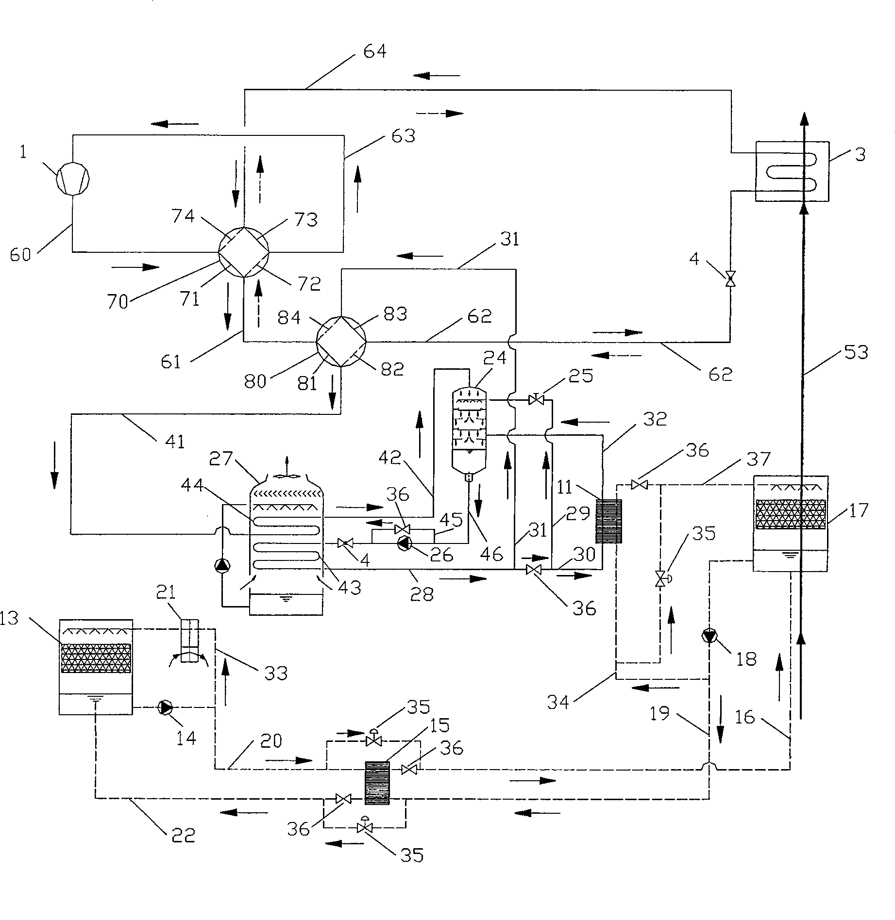
[0022] Such as figure 1 As shown, according to the different working processes in winter and summer, its working process can be divided into summer circulation system and winter circulation system.
[0023] 1. Summer circulatory system
[0024] The summer circulation system consists of five subsystems, which are air handling subsystem, solution dehumidification and regeneration subsystem, refrigeration subsystem, solution cooling subsystem and refrigerant cooling subsystem.
[0025] (1) Air handling subsystem
[0026] It is made up of dehumidifier 17, evaporator 3. The dehumidifier 17 and the evaporator 3 are connected through the air duct 53 to form an air passage in which the air is dehumidified and cooled.
[0027] During work, the processed air first enters the dehumidifier 17 to be dehumidified. After reaching the required humidity, it enters the evaporator 3 to be cooled. After reaching the required temperature, it is sent into the air-conditioned room.
[0028] (2) ...
Embodiment 2
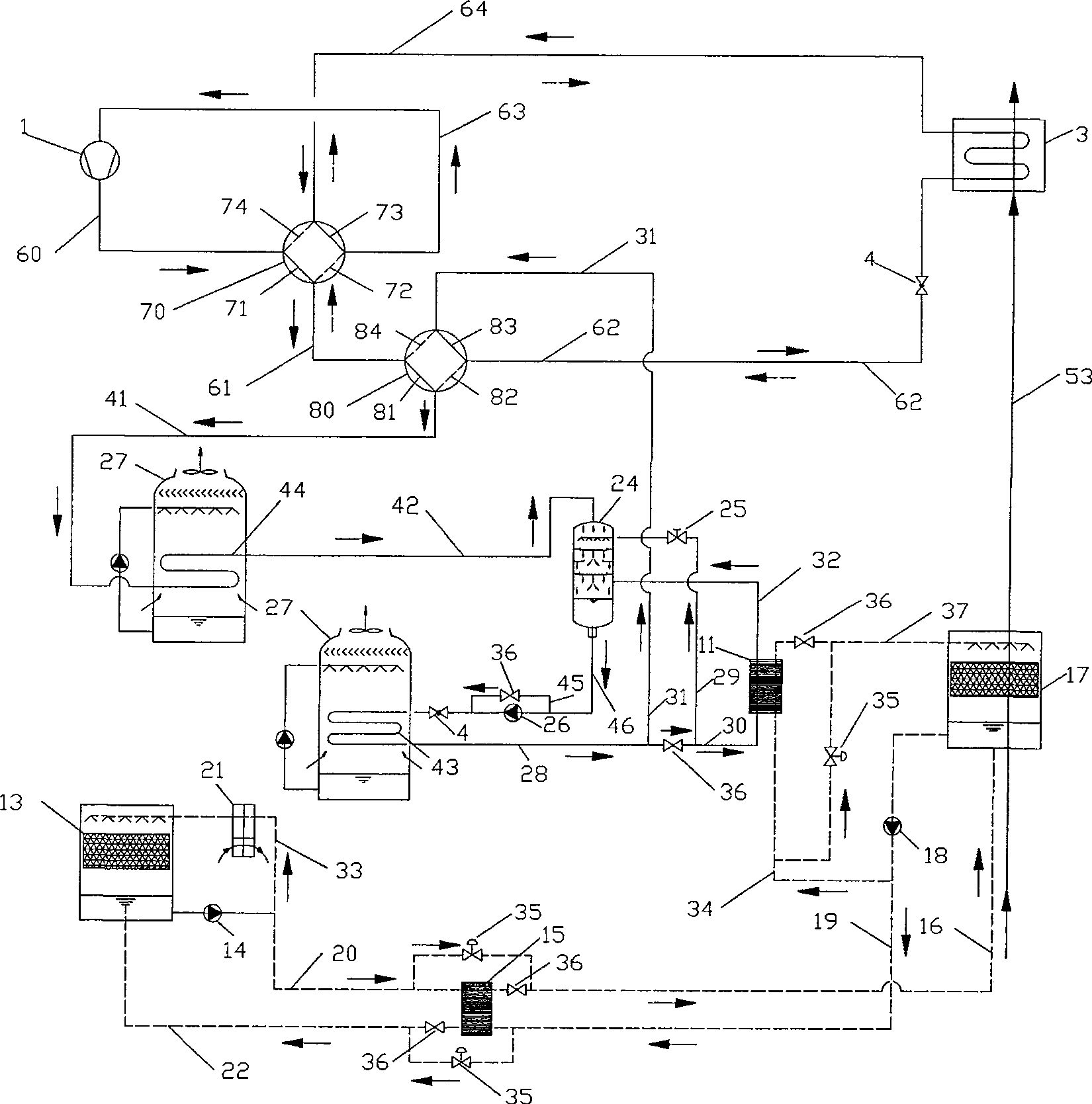
[0084] Example 2 as figure 2 Shown. The only difference between it and Embodiment 1 is: there are two evaporative heat exchangers 27, and a group of heat exchangers are arranged in each evaporative heat exchanger, and the cooling heat exchanger 43 and the condensation heat exchanger 44 are respectively located in it.
[0085] The composition of other equipment is exactly the same. The work flow of the circulation system in winter and summer, and the connection mode of the equipment are also exactly the same as those in Embodiment 1.
[0086] In Embodiment 1 and Embodiment 2, the second throttling mechanism 4 between the cooling heat exchanger 43 of the evaporative heat exchanger 27 and the working medium pump 26 also has the following two arrangements:
[0087] ①The second throttling mechanism 4 can be arranged on the fourteenth pipeline 42 where the direct contact heat exchanger 24 is connected to the condensing heat exchanger 44 of the evaporative heat exchanger 27. At thi...
Embodiment 3
[0091] The difference between it and Embodiment 1 and Embodiment 2 is that only the first throttling mechanism 4 is set in the system, and it is usually set at the second channel 82 and the third channel 83 of the evaporator 3 connected with the second four-way valve 80 . The nineteenth pipeline 62 may also be arranged on the eighth pipeline 31; the first flow direction control valve 36 may not be provided between the fifth pipeline 28, the sixth pipeline 29, and the seventh pipeline 30. During the cycle in winter, a bypass fifteenth pipeline 45 and a second flow direction control valve 36 may also be provided between the suction end and the discharge end of the working fluid pump 26 to reduce the flow resistance of the refrigerant in the pipeline.
[0092] The composition and connection methods of other equipment are the same as those of Embodiment 1 and Embodiment 2. During the circulation process of winter and summer, the first throttling mechanism 4 works normally to thrott...
PUM
 Abstract
Description
Claims
Application Information
 - R&D
- Intellectual Property
- Life Sciences
- Materials
- Tech Scout
- Unparalleled Data Quality
- Higher Quality Content
- 60% Fewer Hallucinations
Browse by: Latest US Patents, China's latest patents, Technical Efficacy Thesaurus, Application Domain, Technology Topic, Popular Technical Reports.
© 2025 PatSnap. All rights reserved.Legal|Privacy policy|Modern Slavery Act Transparency Statement|Sitemap|About US| Contact US: help@patsnap.com


