
Mixed super-resolution optical head

A super-resolution and hybrid technology, applied in the direction of optical recording head, beam guiding device, etc., can solve the problems of affecting the quality of signal reading, affecting the intensity of detection light, and large side lobes, so as to achieve easy reading and detection, and reduce Effect of sidelobe crosstalk and small sidelobe

Inactive Publication Date: 2009-08-12
SHANGHAI INST OF OPTICS & FINE MECHANICS CHINESE ACAD OF SCI +1
View PDF5 Cites 2 Cited by
  • Summary
  • Abstract
  • Description
  • Claims
  • Application Information

AI Technical Summary

Problems solved by technology

Although this structure can compress the central light spot, it will generate large side lobes at the same time, which will cause crosstalk during the signal reading process and affect the signal reading quality
Moreover, since the phase plate is placed behind the beam splitter in this structure, the light returning to the photodetector will be attenuated twice by the phase plate, which will greatly affect the intensity of the detection light.

Method used


Image

  • Mixed super-resolution optical head
  • Mixed super-resolution optical head
  • Mixed super-resolution optical head

Examples


Embodiment Construction

[0023] specific implementation

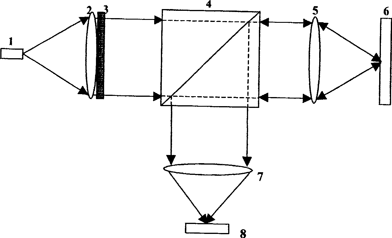
[0024] figure 1 It is a structural principle diagram of a specific embodiment of the present invention. Depend on figure 1 It can be seen that the hybrid super-resolution optical read head of the present invention is composed of a semiconductor laser 1, a collimator lens 2, a hybrid super-resolution phase plate 3, a beam splitter 4, a read-write objective lens 5, a focusing lens 7, and a spot detector 8 , the optical disc 6 is placed behind the read-write objective lens 5, and is characterized in that a hybrid super-resolution phase plate 3 is added in front of the beam splitter 4 and is coaxial with the objective lens 5, and the hybrid super-resolution phase plate can control the passing light Amplitude and phase distribution.

[0025] There are many kinds of hybrid super-resolution phase plates, such as: CN200410066745.4 three-dimensional super-resolution complex amplitude super-resolution filter proposed by Yun Maojin et al.; CN2005100244...


PUM

PropertyMeasurementUnit
sizeaaaaaaaaaa

Abstract

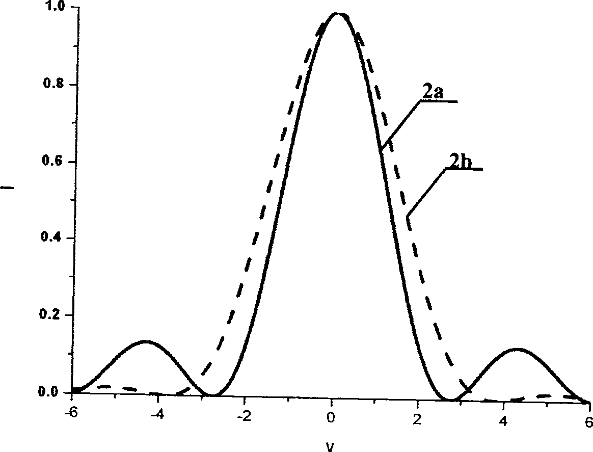
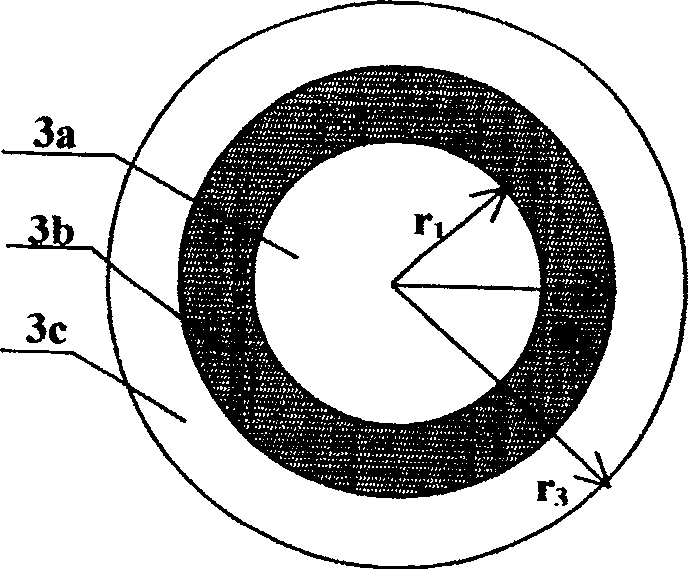
A hybrid super-resolution optical head, which sequentially includes a semiconductor laser, a collimator lens, a beam splitter, a read-write objective lens, a focusing lens and a photodetector, and a super-resolution phase plate placed in the optical path between the collimator lens and the optical disc is The hybrid super-resolution phase plate, the hybrid super-resolution phase plate is a pupil filter with a three-ring structure, and the phase plate is coaxial with the system. The normalized radius of the annulus is: r1=0.49, r2=0.64, r3=1; the phases of the three regions are φ1=0, φ2=π, φ3=0; the transmittances of the three regions are t1=0.23, t2=1 and t3=1. It can simultaneously control the amplitude and phase distribution of passing light. The use of a hybrid super-resolution phase plate instead of a phase-type super-resolution phase plate as in CN200410093317.0 is beneficial in that smaller side lobes of focused light spots can be obtained and signal reading quality can be improved.

Description

Technical field [0001] The high-density disc optical read head uses optical super-resolution technology to increase the storage density of discs. Background technique [0002] With the development of computer multimedia technology and the popularization of computer networks, ultra-high density, ultra-large capacity, and ultra-fast information storage technology has attracted widespread attention. Optical storage technology using photons as information carriers has special advantages that traditional storage technologies do not have. In recent years, it has continuously made major breakthroughs in technology and achieved great success in market applications. In order to further increase the storage density of optical discs, a lot of research work has been done. The most direct way to increase the storage density is to reduce the size of the focused spot, but limited by the diffraction effect, the radius R of the focused spot is proportional to the laser wavelength λ, and inv...

Claims


Application Information

Patent Timeline
Patent Type & Authority Patents(China)
IPC IPC(8): G11B7/12G11B7/135
Inventor 赵晓枫阮昊
Owner SHANGHAI INST OF OPTICS & FINE MECHANICS CHINESE ACAD OF SCI
Learn More