W type flame boiler local ventilation side-proof wall and wing wall water-cooled wall slagging apparatus

A local ventilation and water-cooled wall technology, applied in steam boilers, combustion methods, combustion chambers, etc., can solve problems such as wing wall and side wall slagging, and achieve the effect of preventing slagging

Active Publication Date: 2009-11-04
HARBIN INST OF TECH
View PDF2 Cites 0 Cited by
  • Summary
  • Abstract
  • Description
  • Claims
  • Application Information

AI Technical Summary

Problems solved by technology

[0003] The purpose of the present invention is to solve the problem of slagging of the wing wall and side wall in the existing W-type flame boiler, and further provide a W-type flame boiler local ventilation anti-slagging device for the side wall and wing wall water wall

Method used


Image

  • W type flame boiler local ventilation side-proof wall and wing wall water-cooled wall slagging apparatus
  • W type flame boiler local ventilation side-proof wall and wing wall water-cooled wall slagging apparatus
  • W type flame boiler local ventilation side-proof wall and wing wall water-cooled wall slagging apparatus

Examples


specific Embodiment approach 1

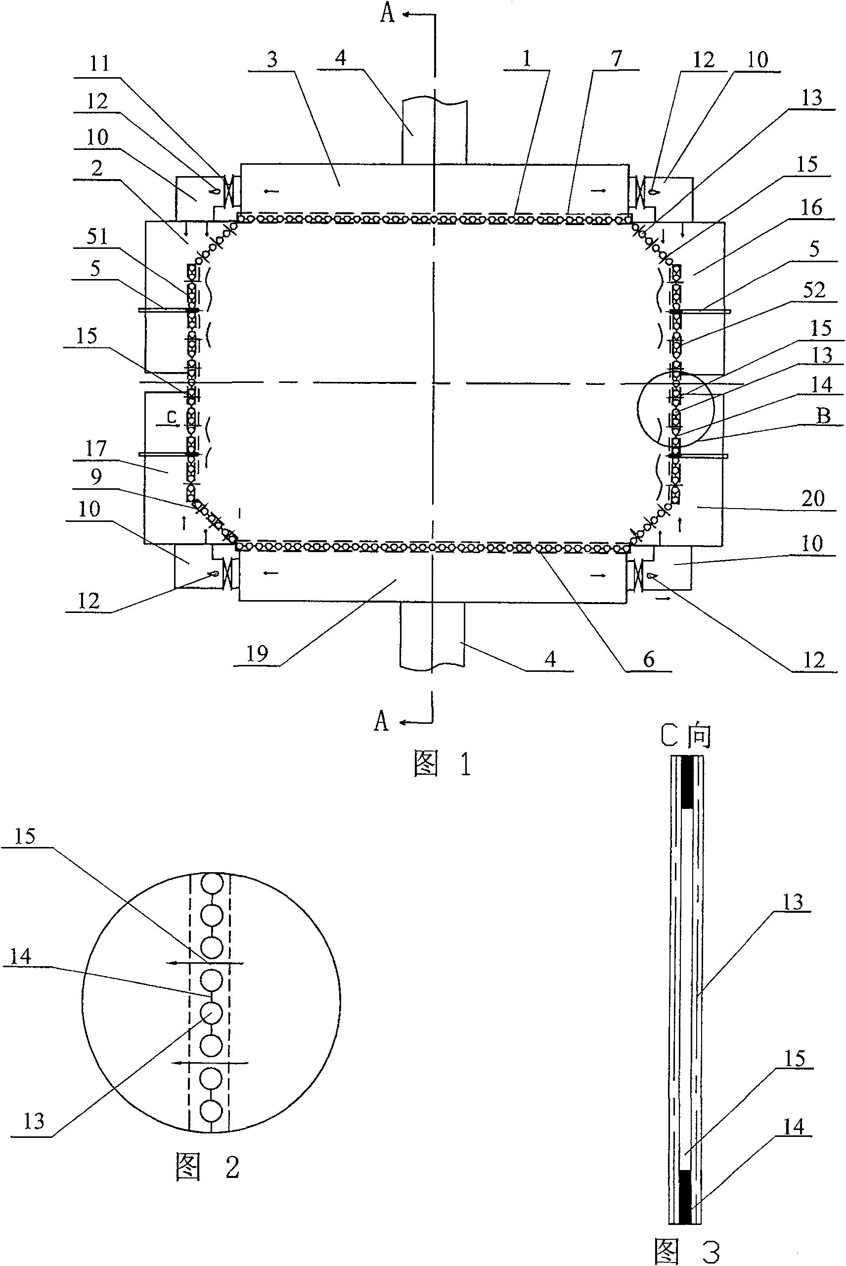
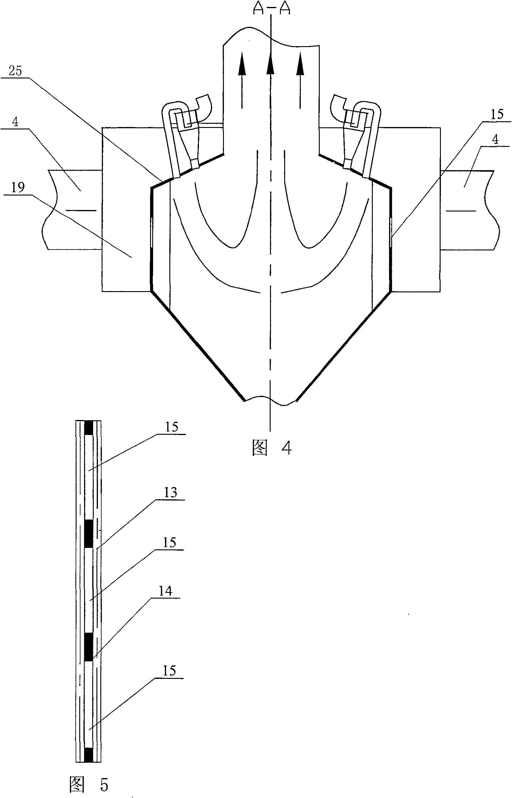
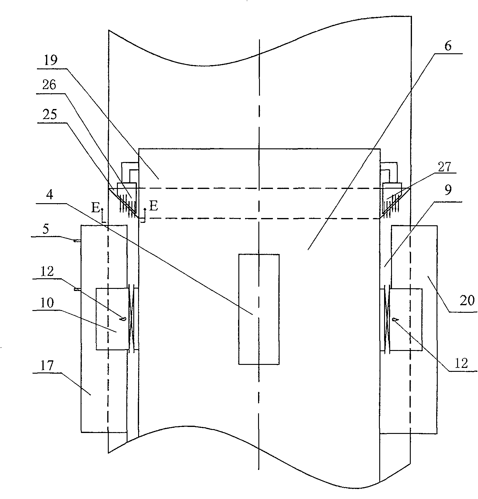
[0007] Specific implementation mode one: combine Figure 1 ~ Figure 4 , Figure 6 , Figure 7 and Figure 9 Describe this embodiment, the anti-slagging device of this embodiment includes a furnace body, a first wall-mounted wind box 2, a first main wind box 3, two secondary air ducts 4, four wall-mounted air ducts 10, a second The wall-attached wind box 16, the third wall-attached wind box 20, the fourth wall-attached wind box 17 and the second main wind box 19; 9 and two furnace arches 25; The wing walls 9 are connected, and the two furnace arches 25 are arranged on the upper end surfaces of the front wall 6, the rear wall 7, the side walls and the four wing walls 9, the front wall 6, the rear wall 7, the two side walls, The four wing walls 9 and the two furnace arches 25 are respectively composed of water-cooled wall tubes 13 and fins 14 arranged alternately and fixed together. The first main air box 3 is arranged on the outside of the rear wall 7, and the second main ai...

specific Embodiment approach 2

[0008] Specific implementation mode two: combination figure 1 To illustrate this embodiment, there are 2 to 7 fins 14 between each wing wall 9 and two adjacent side wall wing wall-attached tuyeres 15 on each side wall in this embodiment. In this embodiment, since only some of the fins 14 are provided with side wall wing wall-attached tuyeres 15, the entire furnace body can be divided into many small pieces. The fin 14 portion of the wall-mounted tuyere 15 may still be slagging, but this slag is a small piece, which will not form a large area of ​​slagging on the entire furnace wall, so that the large slag fire extinguishing phenomenon is not easy to occur. The application of this embodiment on a 300MW boiler burning bituminous coal shows that after adopting this embodiment, the combustion efficiency of the boiler does not decrease, the slagging of the water wall does not occur, and the fire accidents are greatly reduced. Other components and connections are the same as those ...

specific Embodiment approach 3

[0009] Specific implementation mode three: combinationfigure 1 The present embodiment is described, and the wall-attached tuyeres 15 of the side wall and wing wall of this embodiment are evenly distributed on each wing wall 9 and each side wall. The invention patent application publication number as described in the background technology is CN 101050854A, the publication date is October 10, 2007, and the name is "W-type flame boiler for preventing side wall water-cooled wall slagging" is to make the wing wall close to the side wall The water-cooled wall pipe is pulled back to form spouts on both sides of the side wall, and then the wind boxes on the front and rear walls are supplied to the wall here to form an oxidative atmosphere in the side wall area. Anti-slagging method. The disadvantage of this method is that the momentum of the secondary air supplied by the edge of the side wall is weak, and often cannot reach the middle of the side wall, so that this part of the area is ...


PUM


Abstract

The utility model relates to a local ventilation anti-slagging device of a side wall and a wing wall water wall of a W-shaped flame boiler, which relates to a W-shaped flame boiler. Aiming at the problem of slagging in the wing wall and the side wall of the existing W-shaped flame boiler. The first and fourth wall-attached bellows are located at the rear and front sides of the left wall and the corresponding wing walls; the third and second wall-attached bellows are located at the front and rear of the right wall and the corresponding wing walls; the first Between the main bellows and the first and second wall-attached bellows, between the second main bellows and the third and fourth wall-attached bellows are connected through the wall-attached air duct, the first and second main bellows and the secondary air The first and second air supply boxes are connected with the second main air box, the third and fourth air supply boxes are connected with the first main air box, and the fins on the wing wall and the upper part of the side wall are provided with gaps to form the side wall and wing wall The wall-attached tuyere, the fins between the water-cooled wall tubes of the part of the furnace arch close to the wing wall are provided with gaps to form the wing wall-attached tuyere. The invention has the advantages of reasonable structural design and no slagging of wing walls and side walls.

Description

technical field [0001] The invention relates to a W-shaped flame boiler. Background technique [0002] With the development of the power industry and the tense energy situation, W-flame boilers that use low-volatile and difficult-to-combust coals such as anthracite and lean coal have been used more and more, but W-flame boilers generally have problems in operation. The problem of slagging of side wall and wing wall water wall. Slagging refers to the accumulation of molten ash on the heated wall surface due to complex physical and chemical effects and complex hydrodynamic effects. For W-shaped flame boilers burning low-volatile coal such as anthracite and lean coal, the reasons for slagging can be mainly divided into the following three types: 1. The influence of coal quality characteristics; for coal with low ash melting point, if the flame The temperature in the central area is high, and the ash particles are easy to soften or melt and adhere to the heating surface to cau...

Claims


Application Information

Patent Timeline
Patent Type & Authority Patents(China)
IPC IPC(8): F23C3/00F22B31/00
Inventor 李争起任枫陈智超王静杰徐振兴
Owner HARBIN INST OF TECH
Why Eureka
Try Eureka