
Toilet cistern

A toilet and water tank technology, applied in the field of toilet sanitary ware, can solve the problems that are not conducive to the installation and opening and closing of the flushing and discharging mechanism, reduce the effective water storage capacity of the water tank, and occupy more limited space in the water tank, and achieve convenient layout and installation, simple structure, reliable performance

Inactive Publication Date: 2009-12-09
陈定弟
View PDF7 Cites 0 Cited by
  • Summary
  • Abstract
  • Description
  • Claims
  • Application Information

AI Technical Summary

Problems solved by technology

The water level control mechanism of the water tank with this structure has a large shape and complicated parts and components, which not only occupies more limited space in the water tank, but is not conducive to the installation and opening and closing of the flushing and discharging mechanism, and the floating ball also directly reduces the effective water storage capacity of the water tank.
After improvement, some toilets changed the floating ball into a buoy, although the capacity of the water tank can not be affected, but in order to maintain sufficient buoyancy, the volume of the buoy must be larger than the floating ball, and the lever structure still cannot be less. so still unsatisfactory
Chinese patent ZL200620057017.1 "A kind of internal control water inlet valve for toilet water tank" changes the floating ball (pontoon) into an air pressure cup, uses the air pressure cup and the connecting rod control switch assembly to control the water level of the water tank, not only the structure is more and more complicated, but also It does not overcome the defects of the traditional toilet water tank

Method used

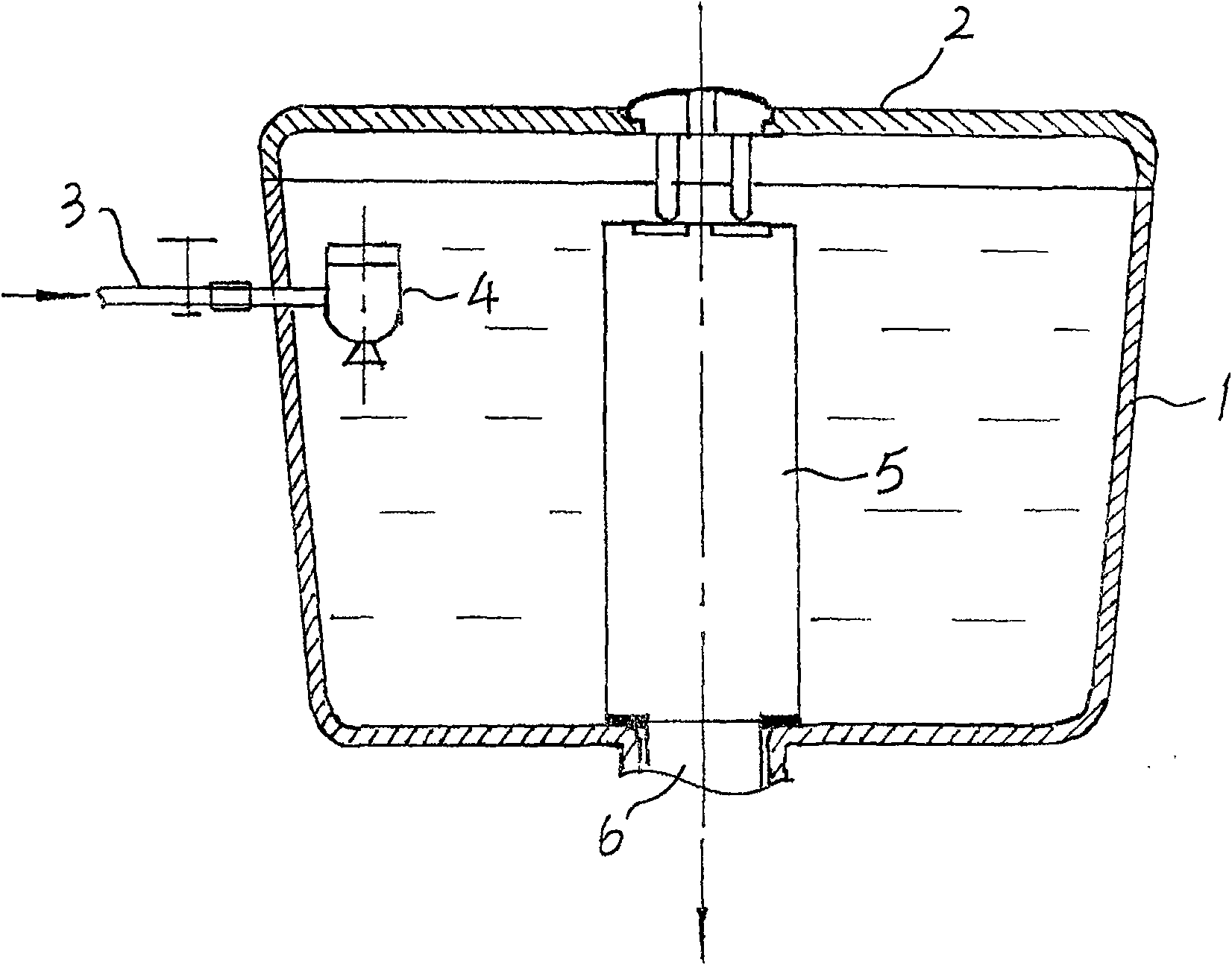
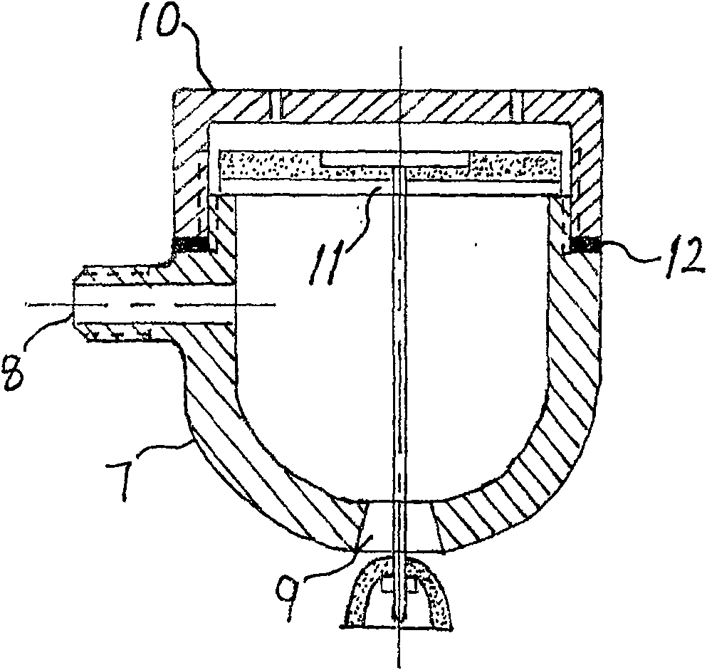
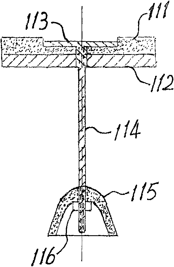

Image

  • Toilet cistern
  • Toilet cistern
  • Toilet cistern

Examples


Embodiment 1

[0011] Embodiment 1 manufactures the standard type toilet water tank of this scheme, structure such as figure 1 Shown:

[0012] According to the traditional ceramic toilet manufacturing process, the water tank body 1, which is connected with the toilet body and has a tap water inlet and a flushing water outlet, and a water tank cover 2 with a mounting hole for the flushing and discharging operation button are made; self-made or purchased According to the prior art two grades (3 liters of urine, 6 liters of stool) of the prior art of national standard production flushing and discharging mechanism 5 and supporting parts are stand-by; figure 2 , image 3 The shown structure is made into a miniature pressure differential water level automatic control valve 4; the water inlet 8 of the miniature pressure differential water level automatic control valve body 7 is connected with the municipal tap water pipe network with a tap water pipe joint 3 with a switch, and then suspended and ...

Embodiment 2

[0013] Embodiment 2 Retrofitting the conventional toilet water tank of the prior art into the toilet water tank of the present invention

[0014] In order to popularize and apply the toilet water tank of this program, it is unrealistic and unscientific to scrap the produced toilet equipped with the float lever type water tank, or to require the user to update and replace. And retrofitting is doable and easy. The specific modification method is to keep the existing technology or the part of the flushing and discharging device of the toilet water tank in use unchanged, remove the water level control mechanism of the floating ball, buoy or other structures, and then according to the tap water inlet orientation of various types of water tanks, connect from From the water inlet of the micro-pressure differential water level automatic control valve valve body to the tap water connection pipe 3 of the water tank water inlet, the micro-pressure differential water level automatic contr...


PUM


Abstract

A toilet water tank, which belongs to toilet sanitary ware, includes a tank body, a tank cover, a tank body water inlet, a flushing water outlet, a flushing water control mechanism, and a water level control mechanism, and is characterized in that the water level control mechanism is a valve body water inlet and After the water inlet of the box body is connected, it is suspended and fixed on the top surface of the valve cover inside the upper mouth of the box body to the level of the highest water level. The miniature pressure differential water level automatic control valve is composed of a valve body, a valve cover and a valve core assembly. . When the water level in the water tank is low or there is no water, the valve core assembly is in the position of opening the water outlet of the valve body due to its own weight, and the tap water enters the water tank through the inner cavity of the valve body. The spool assembly moves up and closes the control valve, realizing automatic control of the water level of the water tank. The toilet water tank of this scheme has a simple structure and is convenient to manufacture, install and use, and is a major innovation of the traditional floating ball lever principle toilet water tank.

Description

technical field [0001] The invention belongs to toilet sanitary ware, in particular to a water storage tank of a toilet. Background technique [0002] Traditional toilet water storage tanks are all manufactured using the floating ball lever principle, using the lifting of the floating ball to drive the needle valve mechanism linked with the lever to open and close the water inlet of the tap water to realize automatic control of the water level of the water tank. The water level control mechanism of the water tank with this structure has a large shape and complicated parts and components, which not only occupies more limited space in the water tank, but is not conducive to the installation and opening and closing of the flushing and discharging mechanism, and the floating ball also directly reduces the effective water storage capacity of the water tank. . After improvement, some toilets changed the floating ball into a buoy. Although it does not affect the capacity of the wa...

Claims


Application Information

Patent Timeline
IPC IPC(8): E03D1/30
Inventor 涂志荣陈定弟沈品辉
Owner 陈定弟
Learn More