
Permanent magnet used for portable nuclear magnetic resonance instrument magnetostatic field generator

A technology of nuclear magnetic resonance and generating devices, which is applied in the direction of instruments, measuring devices, and measuring magnetic variables, etc., which can solve the problems of difficulty in increasing the magnetic field strength, increasing the volume and weight of magnets, and high cost of magnets

Inactive Publication Date: 2009-12-09
INST OF ELECTRICAL ENG CHINESE ACAD OF SCI
View PDF9 Cites 1 Cited by
  • Summary
  • Abstract
  • Description
  • Claims
  • Application Information

AI Technical Summary

Problems solved by technology

This is one of the fundamental reasons for the high cost of magnets
[0015] (2) It is difficult to increase the magnetic field strength
[0016] (3) In the design of the magnet, it is necessary to form a closed magnetic field circuit through the yoke, and it is also necessary to use pole plates or shim rings to improve the uniformity of the magnetic field in the magnet gap, which inevitably adds a lot of ferromagnetic materials, which not only increases the The cost of the instrument increases the volume and weight of the magnet to a great extent, which is not conducive to carrying
[0018] 1) Only with an infinitely long semi-cylindrical magnet along its axial direction can the various quantities of the magnetic field be uniformly distributed, thereby achieving effective compensation for the magnetic field in the hollow cavity of the cylindrical magnet, but in practice, the semi-cylindrical magnet’s The axial length is limited, so this compensation scheme inevitably has systematic errors;
[0019] 2) The magnetic fields at both ends of the semi-cylindrical magnet are divergently distributed in space and have a large flux leakage. Therefore, the requirements for the actual use environment are relatively high, and it still fails to meet the requirements of the portable NMR instrument for the design of the magnet. Flux leakage or no flux leakage requirements

Method used


Image

  • Permanent magnet used for portable nuclear magnetic resonance instrument magnetostatic field generator
  • Permanent magnet used for portable nuclear magnetic resonance instrument magnetostatic field generator
  • Permanent magnet used for portable nuclear magnetic resonance instrument magnetostatic field generator

Examples


Embodiment Construction

[0073] The present invention will be further described below in conjunction with the accompanying drawings and specific embodiments.

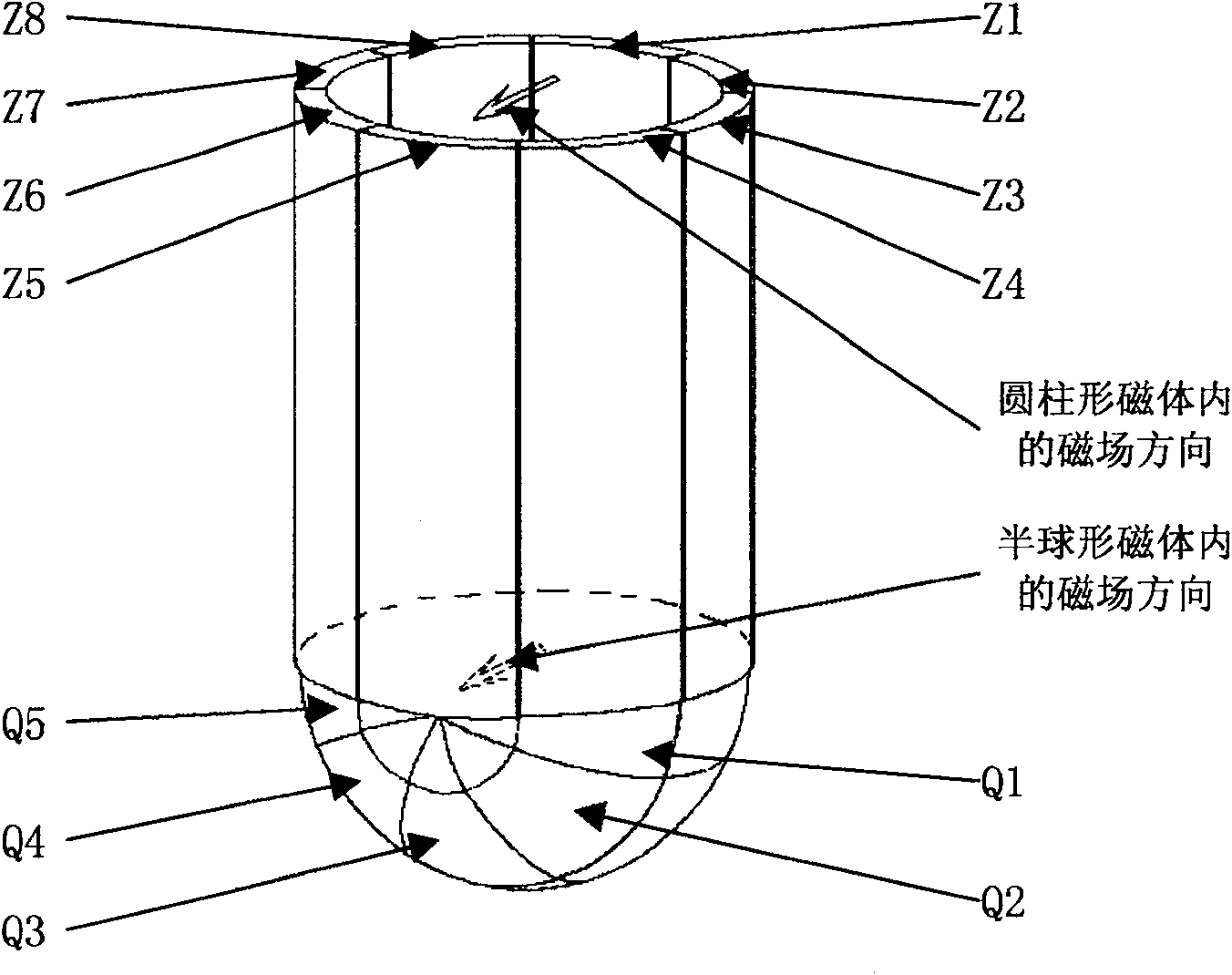
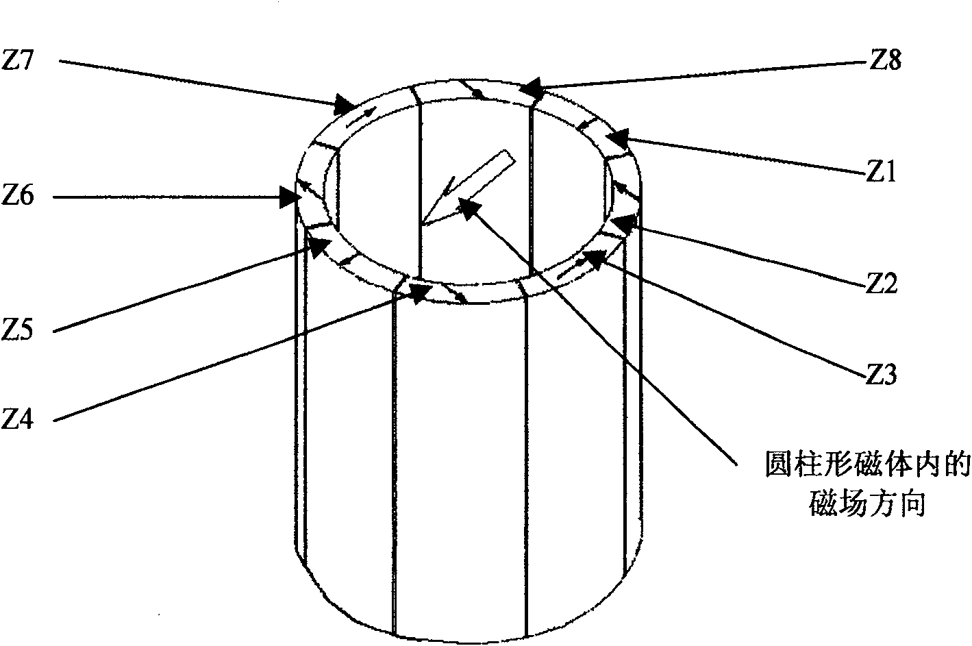
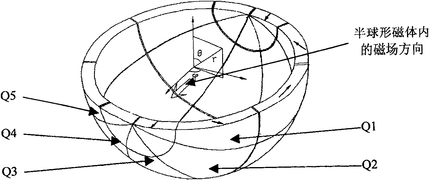
[0074] figure 1 It is a structural schematic diagram of a specific embodiment of the present invention. Such as figure 1 As shown, the magnetic blocks with the same magnetization direction are divided into one group, and a total of 8 groups of cylindrical magnets with a fan-shaped axial section are obtained: Z1, Z2, Z3, Z4, Z5, Z6, Z7, Z8; The diameter parallel to the magnetic field direction in the permanent magnet is the axis, and the ring on the end face is cut into two semicircular rings, and the spherical permanent magnet obtained by rotating the semicircle with the above diameter as the axis at a certain angle is divided into one group, and a total of 5 A set of spherical permanent magnets: Q1, Q2, Q3, Q4, Q5. The direction of the magnetic field in the cylindrical permanent magnet is the same as the direction of the transverse magnetic...


PUM


Abstract

One kind used for then the hold type nuclear magnetic resonance instrument quiet the magnetic field take place equip of always body, from a hollow cylinder form always body and a hollow hemisphere form always body constitute, hemisphere form the stalk of body always cuts one that the noodles folds to impose a cylinder form always a body to carry noodles up. Hollow cylinder form always body from shape homology, the magnetic field strength is equal, magnetizing a direction to revolve a direction for the body double and fan-shaped the body always constitutes. Hemisphere form always body is with the outside path be equal to a cylinder form a body always of outside path, inside path small in cylinder form always body of inside path, the stalk runs parallel with the semicircle wreath of magnetic field direction, the stalk which rounds to run parallel with a magnetic field direction revolves to get of, the hemisphere's form the body always closes the cylinder form body to carry a department at hollow type cylinder form the outside side of the body at the right moment. Hemisphere form always body and cylinder form the body always compensates a cylinder form consistently and in order to a body to always carry the horizontal magnetic field of department in the on-line magnetic field direction of the cylinder stalk inside the chamber.

Description

technical field [0001] The invention relates to a permanent magnet for a nuclear magnetic resonance instrument, in particular to a permanent magnet for a static magnetic field generator for a portable nuclear magnetic resonance instrument. Background technique [0002] In recent years, the field of nuclear magnetic resonance equipment has achieved continuous development, and many important application directions have been proposed and realized continuously. [0003] The current method for measuring drilled core samples is to first obtain cores through field drilling, and then bring the cores back to a laboratory that requires a higher measurement environment for measurement. The disadvantage of this method is that it takes too long from the acquisition of the core to the completion of the measurement, so that the obtained analysis results cannot be effectively used to guide on-site exploration and development due to their poor effectiveness. Therefore, it is of practical si...

Claims


Application Information

Patent Timeline
Patent Type & Authority Patents(China)
IPC IPC(8): G01R33/383
Inventor 陈继忠张一鸣
Owner INST OF ELECTRICAL ENG CHINESE ACAD OF SCI
Learn More