Hartman wave front sensor to realize alignment function by light splitter and testing method thereof

A spectroscopic device and sensor technology, which is used in the testing of machine/structural components, optical instrument testing, optical components, etc. It can solve the problem that the measured beam and the optical axis of the system deviate, it is difficult to adjust the incident wavefront, and the wavefront measurement error becomes larger. and other problems, to achieve the effect of improving measurement accuracy, small detection error, and reducing requirements

Inactive Publication Date: 2009-12-23
INST OF OPTICS & ELECTRONICS - CHINESE ACAD OF SCI
View PDF3 Cites 2 Cited by
  • Summary
  • Abstract
  • Description
  • Claims
  • Application Information

AI Technical Summary

Problems solved by technology

Compared with the incident light path, the measurement field of view of the microlens array is usually very small, and the light spot in the sub-aperture will shift greatly when the measured object changes a small angle, so it is difficult to adjust the incident wavefront into the micro Measuring Field of View of Lens Array
Therefore, in the process of using the Hartmann wavefront sensor, too much energy is spent on alignment; and it is easy to cause the measured beam to deviate from the optical axis of the system, resulting in a larger measurement error of the wavefront

Method used


Image

  • Hartman wave front sensor to realize alignment function by light splitter and testing method thereof
  • Hartman wave front sensor to realize alignment function by light splitter and testing method thereof
  • Hartman wave front sensor to realize alignment function by light splitter and testing method thereof

Examples


Embodiment Construction

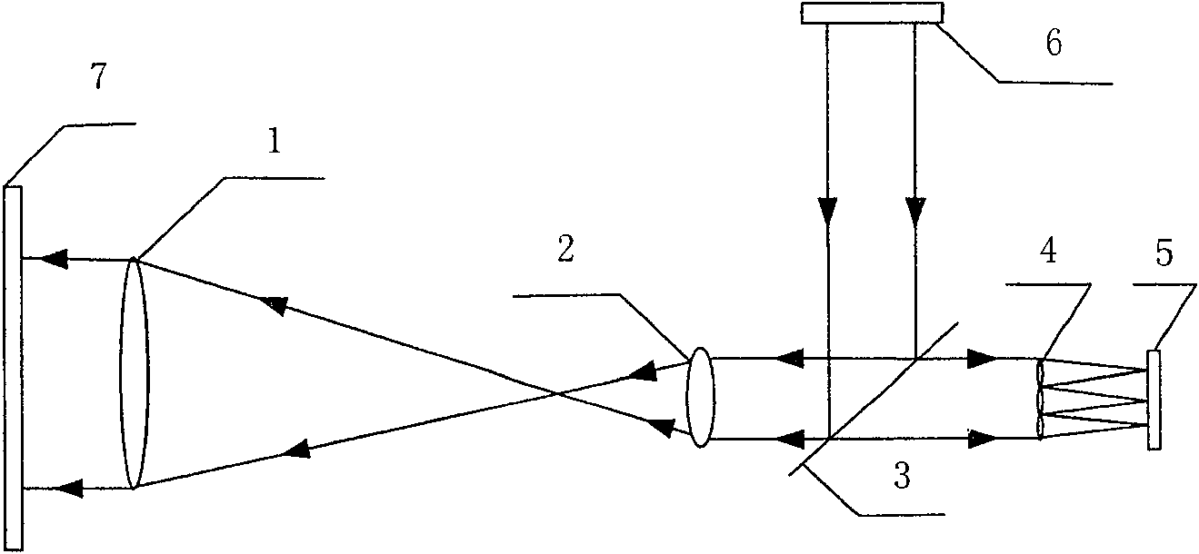
[0017] When the Hartmann wavefront sensor is working, the error of the system itself needs to be calibrated first.

[0018] Such as figure 1 As shown, when calibrating the system error, the beam emitted by the measurement light source system 6 first passes through the beam splitter 3, then passes through the front mirror group 1 and rear mirror group 2 of the beam matching system, and finally exits the system. After being reflected by the standard plane mirror 7, it returns to the system, passes through the beam matching system, the beam splitter 3, and the microlens array 4, and forms an image on the photodetector 5. The position of the standard flat mirror 7 is adjusted to finally make the spot arrangement on the photodetector 5 meet the measurement requirements. But the area of ​​microlens array 4 is about 1cm 2 , is very small compared to the overall optical path, resulting in a small adjustable range of the standard plane mirror 7, and the adjustment is very difficult. ...


PUM


Abstract

Hartmann wavefront sensor and detection method using spectroscopic device to achieve alignment function, two parts of rough alignment and fine alignment are added to the original system, wherein the rough alignment part includes: imaging screen with holes, light splitting The device, the rough alignment detection system, and the fine alignment part include: a focusing lens, a fine alignment beam splitter, and a fine alignment detection system. After the two steps of rough alignment and fine alignment, the incident beam can quickly and easily enter the measurement field of view of the microlens array, and can be strictly coaxial with the system, thereby improving the measurement accuracy of the Hartmann system; At the same time, the Hartmann wavefront sensor can conveniently detect positive lenses, negative lenses, convex mirrors, concave mirrors, plane mirrors, etc. The invention can display the adjustment results in real time, and has the characteristics of being intuitive and easy to understand, thereby reducing the requirements for users and reducing the adjustment time; and the device used in the invention has low specification requirements, low prices, and easy to buy. .

Description

technical field [0001] The present invention relates to a Hartmann wavefront sensor, a precision instrument for measuring the wavefront shape, in particular to a Hartmann wavefront sensor that can simply, quickly and accurately adjust the self-collimated beam or the measured beam to enter the measurement field of view. wavefront sensor. Background technique [0002] The Hartmann wavefront sensor is an instrument that can detect the wavefront shape, and it has been widely used in optical mirror detection, medical instruments and celestial object imaging. In the previous Hartmann wavefront sensor, it usually only includes a measurement light source system, a beam matching system, a microlens array, a photodetector (usually a CCD) and a data processing system. Before the Hartmann wavefront sensor is used, the measured wavefront must be adjusted within the measurement field of view of the microlens array; in the past, the adjustment was made by observing the spot position in th...

Claims


Application Information

Patent Timeline
Patent Type & Authority Patents(China)
IPC IPC(8): G01M11/00G01M11/02G01M19/00G01J9/00G01B11/00G02B27/10G02B27/00G02B7/02G01M99/00
Inventor 李华强饶学军姜文汉鲜浩杨泽平饶长辉
Owner INST OF OPTICS & ELECTRONICS - CHINESE ACAD OF SCI
Why Eureka
Try Eureka