Method of industrial producing fine powder or powder sizeg and its multifunction fine powder grinding series equipment

A micro-powder, multi-functional technology, applied in the multi-functional micro-pulverizing series equipment, industrial production of micro-powder or powder slurry field, can solve the problems of complex equipment structure, large vibration and low technology integration.

Inactive Publication Date: 2007-07-18
何永峰
View PDF0 Cites 9 Cited by
  • Summary
  • Abstract
  • Description
  • Claims
  • Application Information

AI Technical Summary

Problems solved by technology

At home and abroad, airflow pulverizers, roller press pulverizers, media motion pulverizers, mechanical impact pulverizers, etc. are mainly used to pulverize materials through impact, shearing, friction and other mechanical forces. The equipment structure is complex. High energy consumption per unit output, high wear, low production capacity, backward automatic control ability, low technology integration, poor matching, the fineness of the crushed particle size is 40-10μm (380-1250 mesh); energy consumption 100-160KWN / T ; Unit output 1.5-0.05T / h
Some even have large vibrations, loud noises, a lot of dust, and the crushing environment is daunting

Method used


Image

  • Method of industrial producing fine powder or powder sizeg and its multifunction fine powder grinding series equipment
  • Method of industrial producing fine powder or powder sizeg and its multifunction fine powder grinding series equipment
  • Method of industrial producing fine powder or powder sizeg and its multifunction fine powder grinding series equipment

Examples


Embodiment 1

[0054] The slag with medium Mohs hardness is industrially produced fine powder according to the process flow of the above-mentioned Figure 1 and the three-stage progressive pulverizer.

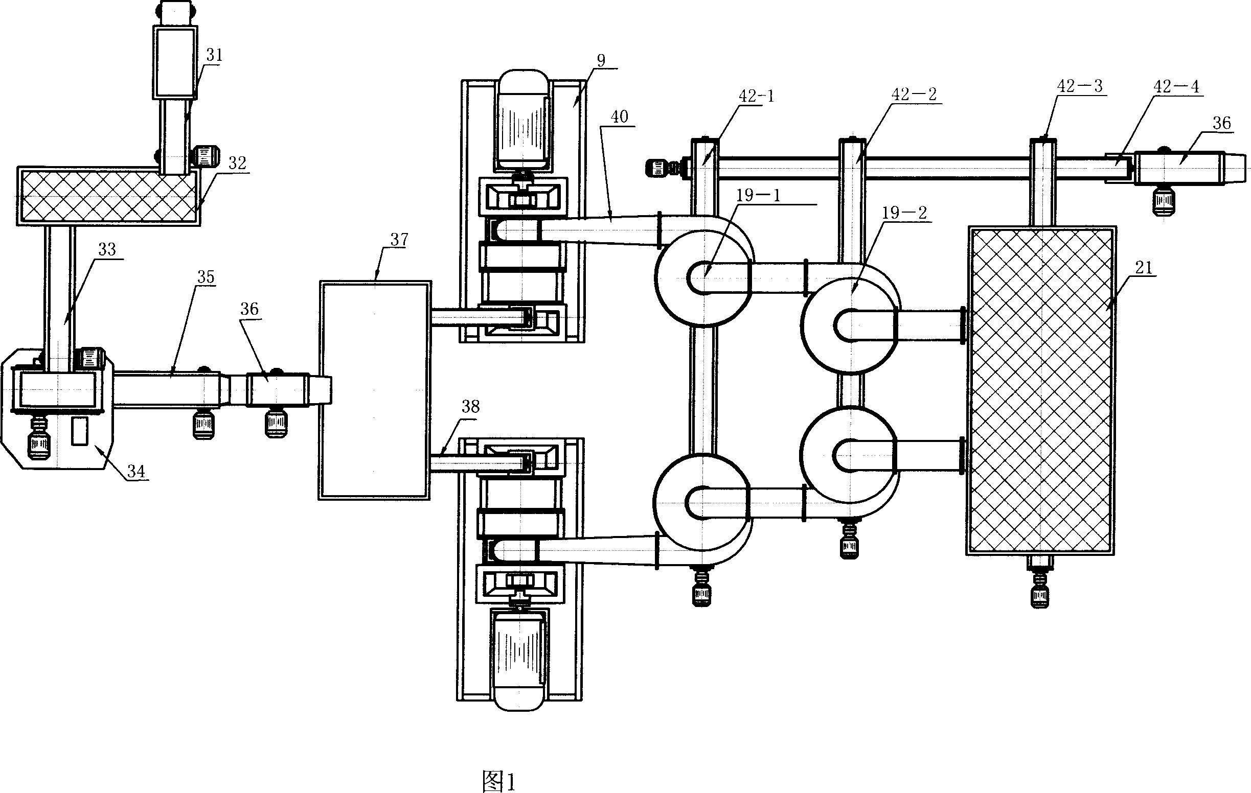
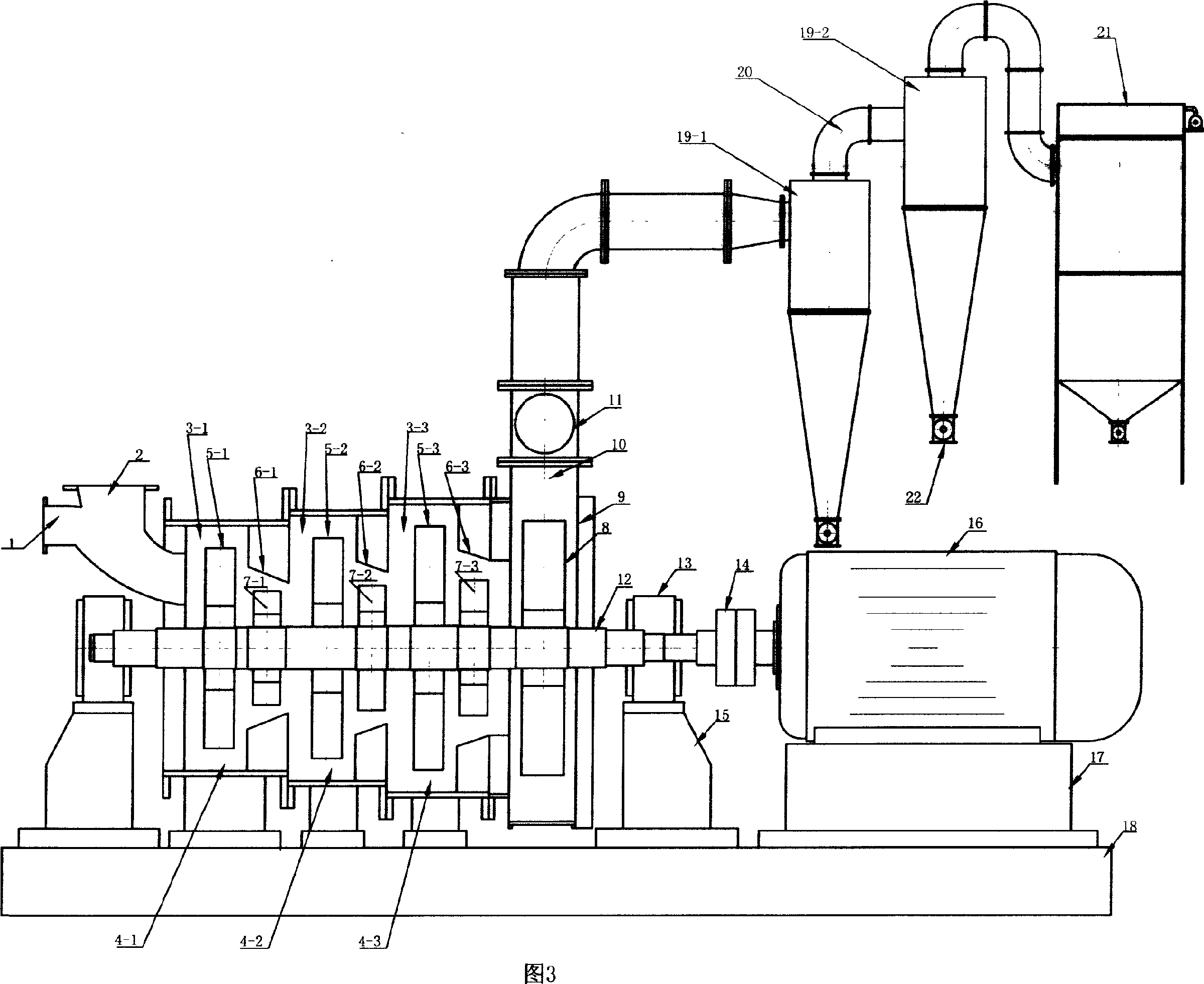
[0055]The raw material enters the screening machine 32 from the raw material conveyor 31, removes large pieces of material, and then passes through the iron removal conveyor 33, removes iron, enters the coarse crusher 34, and coarsely crushes the raw material to slag material of ≤3mm, and then passes through the conveyor 35. The elevator 36 enters the feed bin 37, and then is sent to the feed port 2 of the 3-stage flow-by-flow pulverizer through the quantitative feeder 38, so that the machine can automatically inhale and perform 3-stage pulverization, and the pulverized fine powder is combined with the air Through the discharge pipe 10, it first enters the material collector 19-1, and then enters the material collector 19-2. The wind and residual micropowder from the material collector 19-2 ent...

Embodiment 2

[0059] The steps of embodiment 2 are the same as those of embodiment 1, except that the present embodiment uses a 6-stage progressive pulverizer for pulverization, and the results are listed in Table 2.

Embodiment 3

[0061] Carry out industrial production of fine powder slurry according to the flow process of above-mentioned Fig. 2 and 3 grades of flow-by-flow pulverizers.

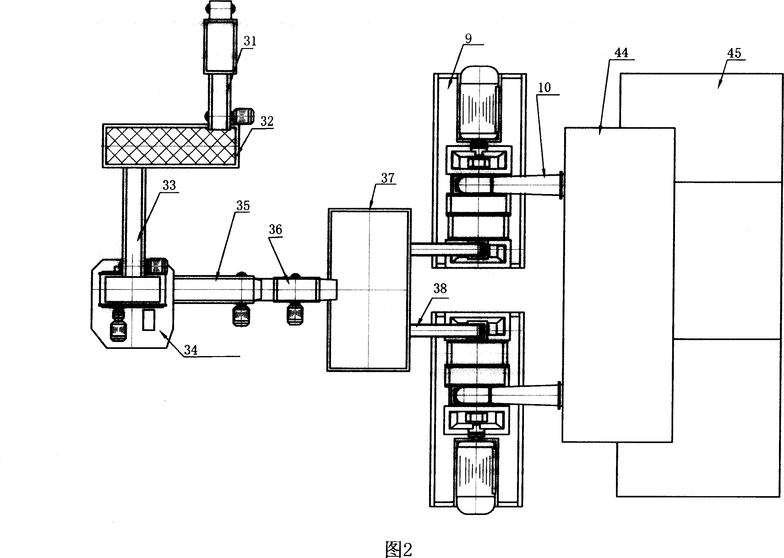
[0062] The slag raw material enters the screening 32 from the raw material conveyor 31, removes large pieces of material, and then passes through the iron removal conveyor 33, removes iron, enters the coarse crusher 34, and coarsely crushes the raw material to a slag material of ≤3mm, and then passes through the conveyor 35. The elevator 36 enters the feed bin 37, and then is sent to the feed port 2 of the multifunctional flow-by-flow pulverizer through the quantitative feeder 38, so that the machine can automatically inhale and pulverize, and the pulverized fine powder is discharged together with the air. The pipe 10 automatically enters the spray chamber 44 and sprays with water. The micropowder and water sink to the bottom of the chamber together, slide into the slurry pool through a landslide, and become slurry afte...


PUM

PropertyMeasurementUnit
Granularityaaaaaaaaaa

Abstract

A process for industrially preparing superfine powder or powder slurry includes such steps as breaking raw material to become particles equal to or less than 3 mm, multi-stage pulverizing to become superfine powder, and directly mixing it with water to become powder slurry. Its multifunctional superfine pulverizing system is also disclosed.

Description

technical field [0001] The invention relates to the field of crushing engineering, in particular to a method for industrially producing fine powder or powder slurry and a series of multifunctional fine crushing equipment. technical background [0002] At present, the large-scale industrial production of fine powder, such as the annual output of hundreds of thousands of tons or several million tons of each production line and the matching of large-scale fine grinding equipment (single machine annual output of hundreds of thousands of tons), has not been reported so far. At home and abroad, airflow pulverizers, roller press pulverizers, media motion pulverizers, mechanical impact pulverizers, etc. are mainly used to pulverize materials through impact, shearing, friction and other mechanical forces. The equipment structure is complex. High energy consumption per unit output, high wear, low production capacity, backward automatic control ability, low technology integration, poor...

Claims


Application Information

Patent Timeline
IPC IPC(8): B02C13/00B02C13/28B02C13/282B02C13/286B02C13/30B02C23/08B02C25/00
Inventor 何永峰
Owner 何永峰
Why Eureka
Try Eureka