Single circulating heat pump generating apparatus

A power generation device, single-cycle technology, applied in electromechanical devices, steam engine devices, electrical components, etc., can solve the problems of inappropriate popularization and low system efficiency, and achieve the effect of alleviating atmospheric warming and energy crisis.

Inactive Publication Date: 2007-07-18
李治国
View PDF1 Cites 9 Cited by
  • Summary
  • Abstract
  • Description
  • Claims
  • Application Information

AI Technical Summary

Problems solved by technology

Chinese patent 200410097600.0 discloses an energy source technical solution using a heat pump and a double-fluid cycle power generation device. It uses two closed-circuit circulation systems, one for heat collection and one for a heat engine. It does not have a heat feedback structure, but uses a heat engine way to utilize, so the system is extremely inefficient
At the same time, the isobutane or isopentane it uses is a flammable gas and should not be popularized.

Method used


Image

  • Single circulating heat pump generating apparatus
  • Single circulating heat pump generating apparatus
  • Single circulating heat pump generating apparatus

Examples


Embodiment 1

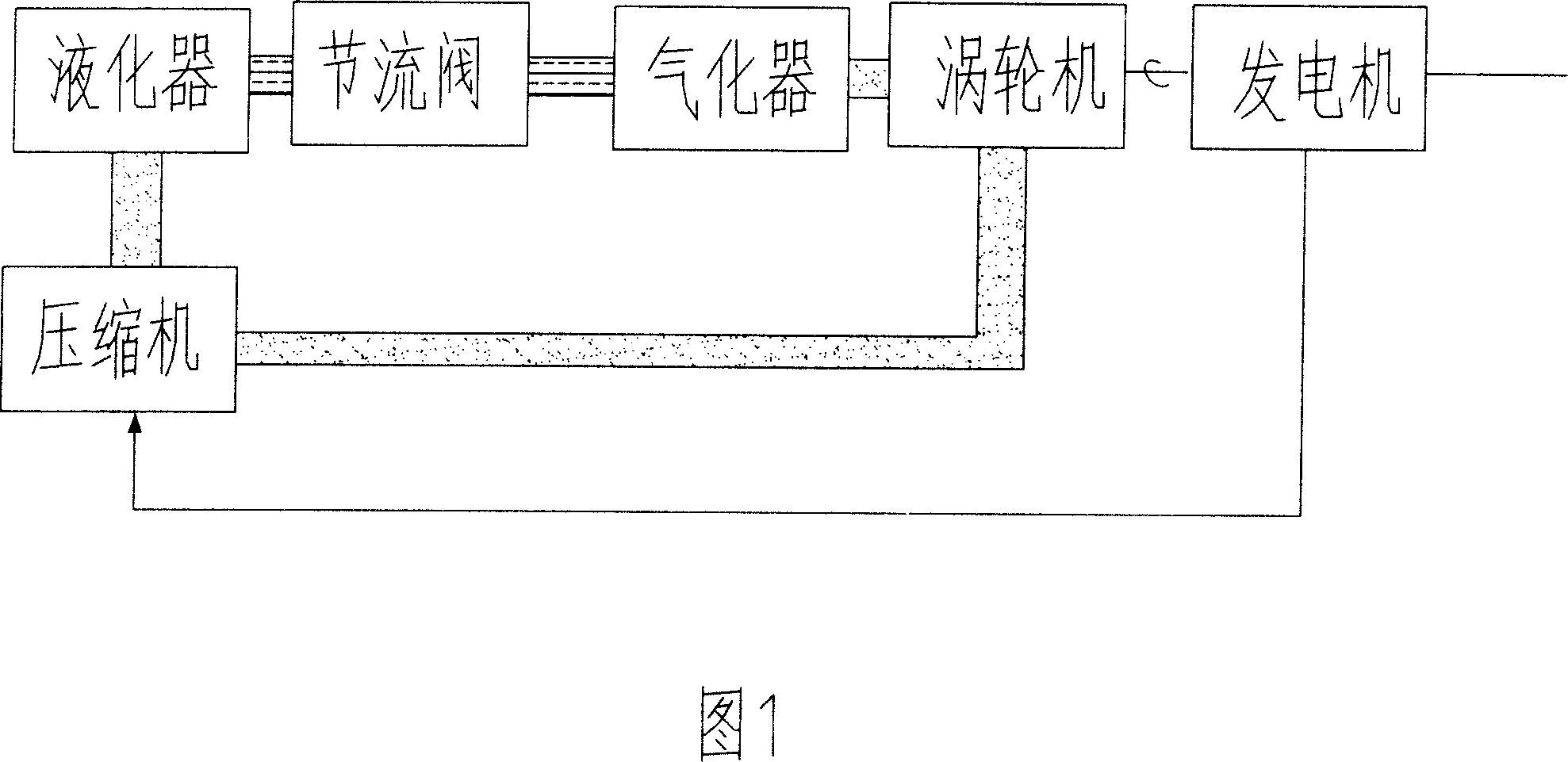
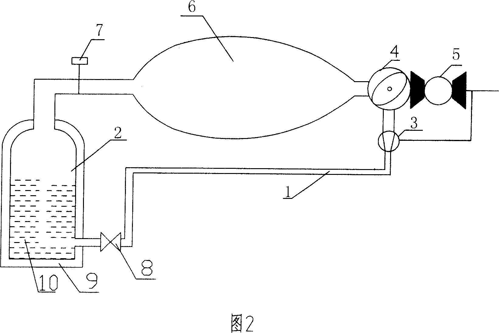
[0016] Embodiment 1 is a kind of non-heat exchange type single-cycle heat pump power generation device (as shown in Figure 2 ) provided according to the system block diagram shown in Figure 1, which consists of a liquefier 1, a vaporizer 2, a compressor 3, and a turbine 4 , generator 5, decompression and speed-up special-shaped pipe 6, airtight valve 7, throttle valve 8, the gasifier 1 is an external insulation layer 9, a built-in liquid working medium 10 and has a gas chamber and a high-pressure gas exhaust port The barrel-like structure of the container, its high-pressure gas exhaust port is connected to the decompression and speed-up special-shaped pipe 6 through the pipeline and the air-tight valve 7 installed on it, and the high-speed air outlet of the decompression and speed-up special-shaped pipe 6 is connected to the turbine 4 , the power output shaft of the turbine 4 is connected to the generator 5, its exhaust gas outlet is connected to the compressor 3, and the high-...

Embodiment 2

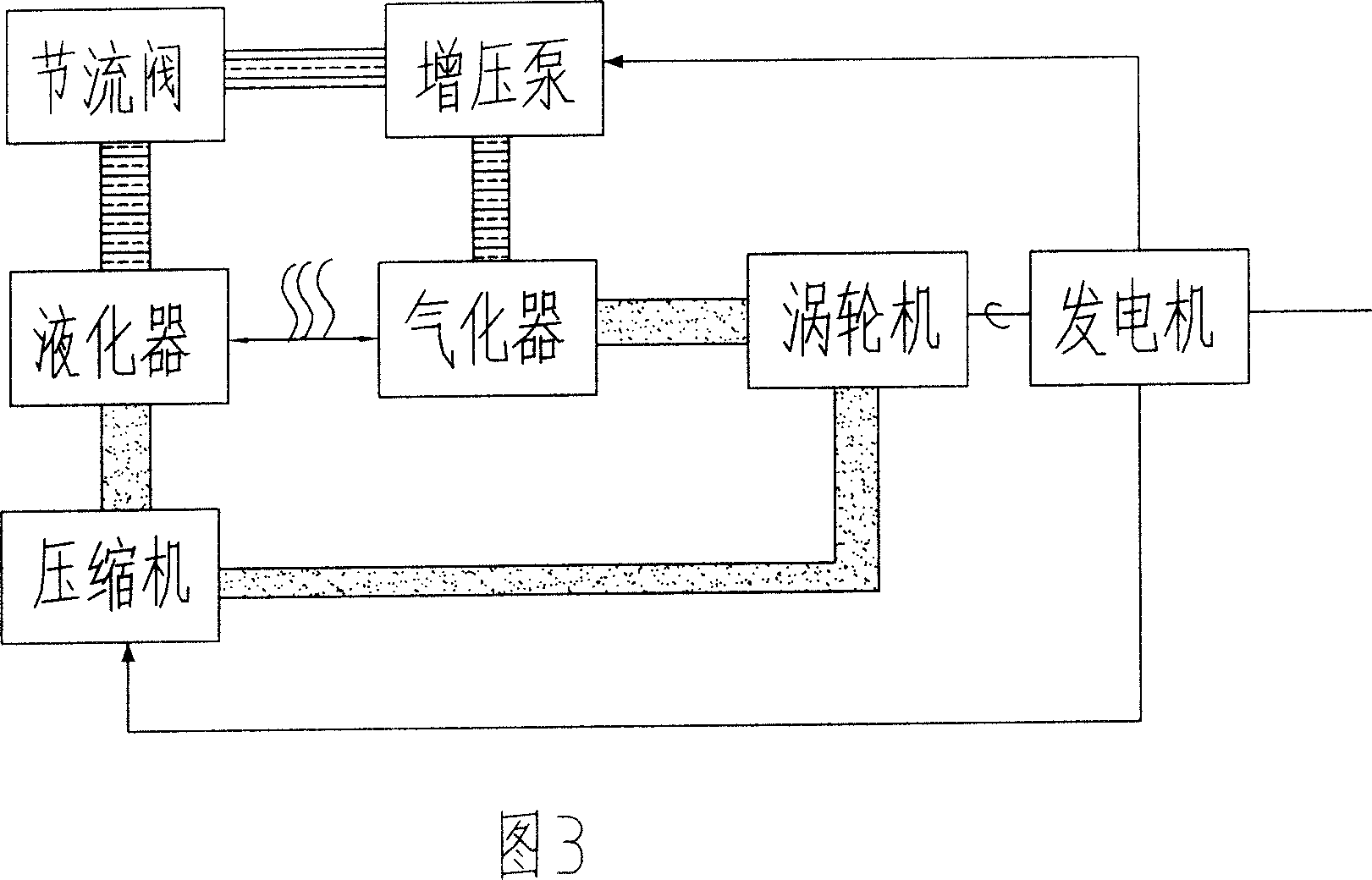
[0019] Embodiment 2 is a kind of internal exchange type single-cycle positive feedback heat pump power generation device (as shown in Figure 4) provided according to the system block diagram shown in Figure 3, which consists of a liquefier 1, a vaporizer 2, a compressor 3, a turbine 4. Generator 5, airtight valve 7, throttle valve 8, booster pump 11 constitute. This gasifier 2 is a container with a barrel structure with an external insulation layer 9, a liquid working medium 10 inside, and an air chamber and a high-speed air outlet. 4 is connected, the power output shaft of the turbine 4 is connected to the generator 5, and its exhaust gas outlet is connected to the compressor 3, and the high-temperature and high-pressure gas outlet of the compressor 3 is connected to the liquefier 1, and the liquefier 1 and the vaporizer 2 form a thermal Exchanger, liquefier 1 can be a spiral tube or a pipe with cooling fins, its main body is placed in the liquid working medium 10 of the vapo...

Embodiment 3

[0022] Embodiment 3 is an externally heated single-cycle positive feedback heat pump power generation device (as shown in FIG. 5 ) according to the system structure shown in FIG. 3 . The difference from Example 1 is that, in addition to a liquefier 1, a vaporizer 2, a compressor 3, a turbine 4, a generator 5, an airtight valve 7, a throttle valve 8, and a booster pump 11, it also has a heating Chamber 12, the heating chamber 12 has a special-shaped tubular structure, one end of which is connected to the exhaust port of the gasifier 2, and the other end is connected to the turbine 4, and the main part of the liquefier 1 is wound around the casing of the heating chamber 12 in the form of a coil Outside, it forms a heat exchanger with the heating chamber 12, and the output port of the normal temperature liquid working medium of the liquefier 1 is connected with the vaporizer 2 through the pipeline and the throttle valve 8 and the booster pump 11 installed on it.

[0023] Working ...


PUM


Abstract

The present invention relates to heat pump power generator, and is especially one kind of single cycle heat pump power generator. The single cycle heat pump power generator includes one gasifier utilizing disorder heat energy in the air as energy source to gasify the liquid working medium and to generate high speed gas flow, one turbogenrator set powered with the high speed gas flow to convert the mechanical energy into electric energy, one compressor to compress the off gas from the turbine into high temperature and high pressure gas and to convey the high temperature and high pressure gas to the liquefier connected to the gasifier for heat exchange, and one booster pump to convey the normal temperature liquid after heat exchange to the gasifier. The present invention has only one cycle loop for both heat collection and generating electricity.

Description

Technical field: [0001] The invention relates to a heat pump power generation device, in particular to a single cycle heat pump power generation device. Background technique: [0002] The traditional power generation device uses a part of the ordered energy (coal, oil) to output electric power, and the other part is used as the driving force of the system, and finally returns to the air in the form of heat dissipation. Obviously it requires conventional fuel, emits harmful gases into the air, and consumes a lot of energy. The heat pump power generation device uses the heat in the air as the energy source. After the system is running, there is surplus power output, that is, the disordered heat energy in the air is converted into orderly electrical energy. Chinese patent 200410097600.0 discloses an energy source technical solution using a heat pump and a double-fluid circulation power generation device. It uses two closed-circuit circulation systems, one for heat collection a...

Claims


Application Information

Patent Timeline
Patent Type & Authority Applications(China)
IPC IPC(8): F01K25/06H02K7/18
CPCF01K25/10F03G7/10
Inventor 李治国李天佐李天时
Owner 李治国
Why Eureka
Try Eureka