Prism, prism production method, optical pick-up and liquid crystal projector

A manufacturing method and prism technology, applied in prisms and other directions, can solve problems such as uneven thickness, inability to perform optical functions, inability to reduce stress, etc.

Active Publication Date: 2007-07-18
FUJI PHOTO OPTICAL CO LTD
View PDF1 Cites 5 Cited by
  • Summary
  • Abstract
  • Description
  • Claims
  • Application Information

AI Technical Summary

Problems solved by technology

The problem is distortion on the base member due to the stress of the dielectric multilayer
There is a problem that the optical function is degraded due to this aberration, or the prescribed optical function cannot be exhibited.
In contrast, when a dielectric multilayer film is formed on the inclined surface of a triangular prism-shaped base member, the opposite side is separated from the midpoint, and the thickness changes continuously, so the thickness is not uniform. Stress forms a dielectric monolayer film, and cannot reduce the stress

Method used


Image

  • Prism, prism production method, optical pick-up and liquid crystal projector
  • Prism, prism production method, optical pick-up and liquid crystal projector
  • Prism, prism production method, optical pick-up and liquid crystal projector

Examples


no. 1 Embodiment

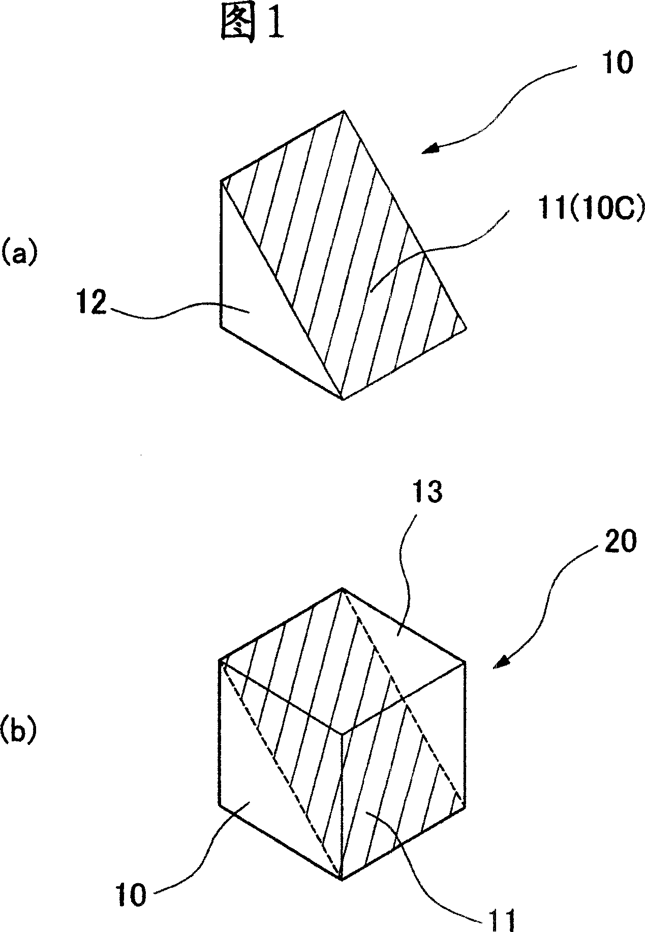
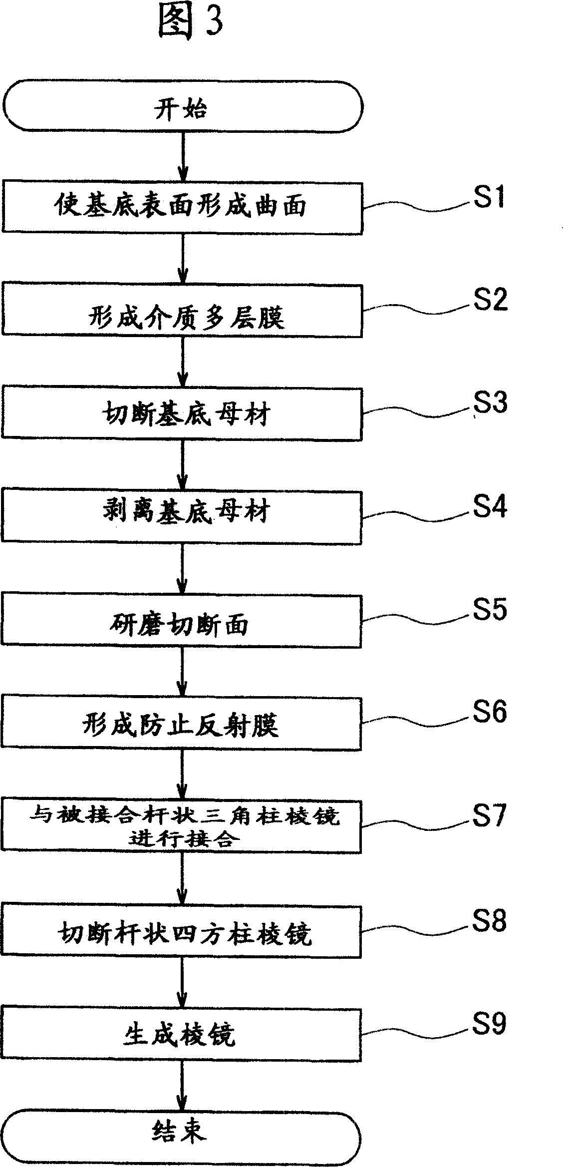
[0047] The present embodiment will be described below with reference to the flowchart in FIG. 3 . In this example, the final purpose is to manufacture the cubic square prism 25 (hereinafter simply referred to as "prism 25") of FIG. 7(b) in the above-mentioned embodiment. Furthermore, the prism 25 of this embodiment functions as a polarization beam splitter. Therefore, the dielectric multilayer film 11 formed on the prism 25 is a polarization separation film that uses the polarization direction of incident light to divide transmission and reflection. Of course, dichroic mirrors, reflective mirrors, etc. may be used instead of polarization beam splitters.

[0048] As mentioned above, the prism 25 functioning as a polarizing beam splitter needs to increase the number of layers of the dielectric multilayer film 11 functioning as a polarized light splitting film in order to be compatible with laser light having three wavelengths: CD, DVD, and large-capacity optical disc. Therefor...

no. 2 Embodiment

[0067] The second embodiment will be described below. In the above-mentioned first embodiment, in order to produce the rod-shaped triangular prism 60, the base base material 50 is cut from the surface opposite to the surface on which the dielectric multilayer film 11 is formed to form a zigzag shape. However, in the present embodiment, the rod-shaped triangular prism 60 is produced from the base base material 50 by a method different from that in the first embodiment.

[0068] As shown in FIG. 8(a), the large base base material 50 of the first embodiment is cut into a rectangular shape. In this way, many elongated rectangular base bodies 51 having a rectangular shape as shown in (b) of the same figure can be produced (rectangular shape cutting step). In the case of the present embodiment in which the finally produced prism 25 is a cube, the elongated rectangular base body 51 is formed as an elongated base body with a square cross section. Therefore, in the 2 ridgelines of th...

no. 3 Embodiment

[0071] An example of an optical pickup using the prism 25 used as a polarization beam splitter manufactured in the first embodiment or the second embodiment will be described below. In FIG. 9 , the optical pickup of this embodiment has structurally: a light source 101 , a polarization beam splitter 102 , a λ / 4 wavelength plate 103 , an objective lens 104 and a photodetector 105 . One of the laser beams of three wavelengths, CD, DVD, and large-capacity optical disc, is selectively oscillated from the light source 101 . The polarizing beam splitter 102 is the same as the prism 25 described in the first and second embodiments above. In this embodiment, it is used as a polarization beam splitter compatible with three wavelengths. Therefore, in the polarized beam splitter 102, a polarized light splitting film is formed which divides transmission and reflection using the polarization direction of incident light (same as the dielectric multilayer film 11 of the first and second embo...


PUM


Abstract

The aim of the invention is to fabricate lens with high plane precision. The method includes: preparing a glass equipment 12 in a triangular prism shape and forming a medium multilayer film 11 on a film forming face 10C of the glass equipment 12. The forming face 10 is distorted by stress generated on the medium multilayer film 11, but before the medium multilayer film 11 is formed, a curved surface shape is preformed on the film forming face 10C, so that a concave or a convexity is formed in a direction opposite to the stress generated on the medium multilayer film 11. In addition, the curved surface shape is formed on the film forming face 10C according to a complanation curvature of the film forming face 10C when the medium multilayer film 11 is formed. Due to correction is performed while the medium multilayer film 11 is formed on the film forming face 10C, complanation of the film forming face 10C can be achieved. Thereby, the medium multilayer film 11 will not distort and problems such as aberration and the like can be eliminated.

Description

technical field [0001] The present invention relates to a method of manufacturing a prism formed with a dielectric multilayer film, a prism, an optical pickup, and a liquid crystal projector. Background technique [0002] One of the main components of an optical pickup used for information reproduction and recording of CDs (Compact Discs) and DVDs (Digital Video Discs) is a polarizing beam splitter. A polarizing beam splitter is an optical element that has the optical property of dividing transmission and reflection using the polarization direction of incident light. A polarizing beam splitter is generally composed of a cube-shaped prism, and its material is a base member such as a glass substrate to form a polarized light splitting film having the above-mentioned optical characteristics. In addition, a dichroic film is formed on the prism to be used as a dichroic prism, and a total reflection film is formed to be used as a reflecting mirror. [0003] As described above, b...

Claims


Application Information

Patent Timeline
Patent Type & Authority Applications(China)
IPC IPC(8): G02B5/04
Inventor 小仓寿人松叶孝彦小宫启二大塚聪美关口隆史
Owner FUJI PHOTO OPTICAL CO LTD
Why Eureka
Try Eureka