Device for implementing shaping high power caser diode pile light beam

A laser diode and beam shaping technology, which is applied in the application field of laser technology to achieve the effect of eliminating dark areas and improving beam quality

Inactive Publication Date: 2007-07-18
SHANXI FEIHONG MICRO NANO PHOTOELECTRONICS SCI & TECH
View PDF0 Cites 23 Cited by
  • Summary
  • Abstract
  • Description
  • Claims
  • Application Information

AI Technical Summary

Problems solved by technology

[0005] However, the three beam shaping methods mentioned above are only aimed at the beam shaping of a single la...

Method used


Image

  • Device for implementing shaping high power caser diode pile light beam
  • Device for implementing shaping high power caser diode pile light beam

Examples


Embodiment Construction

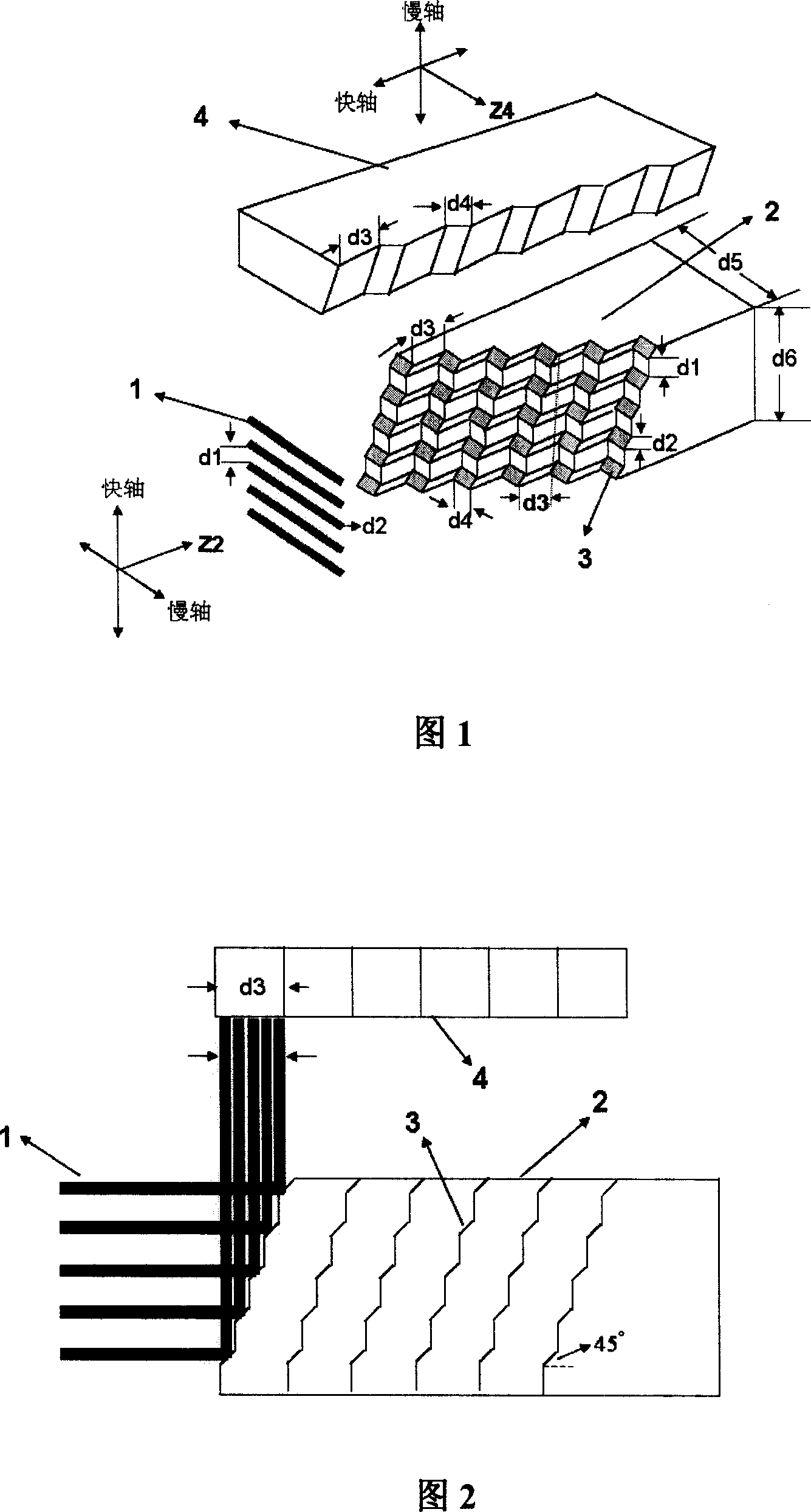
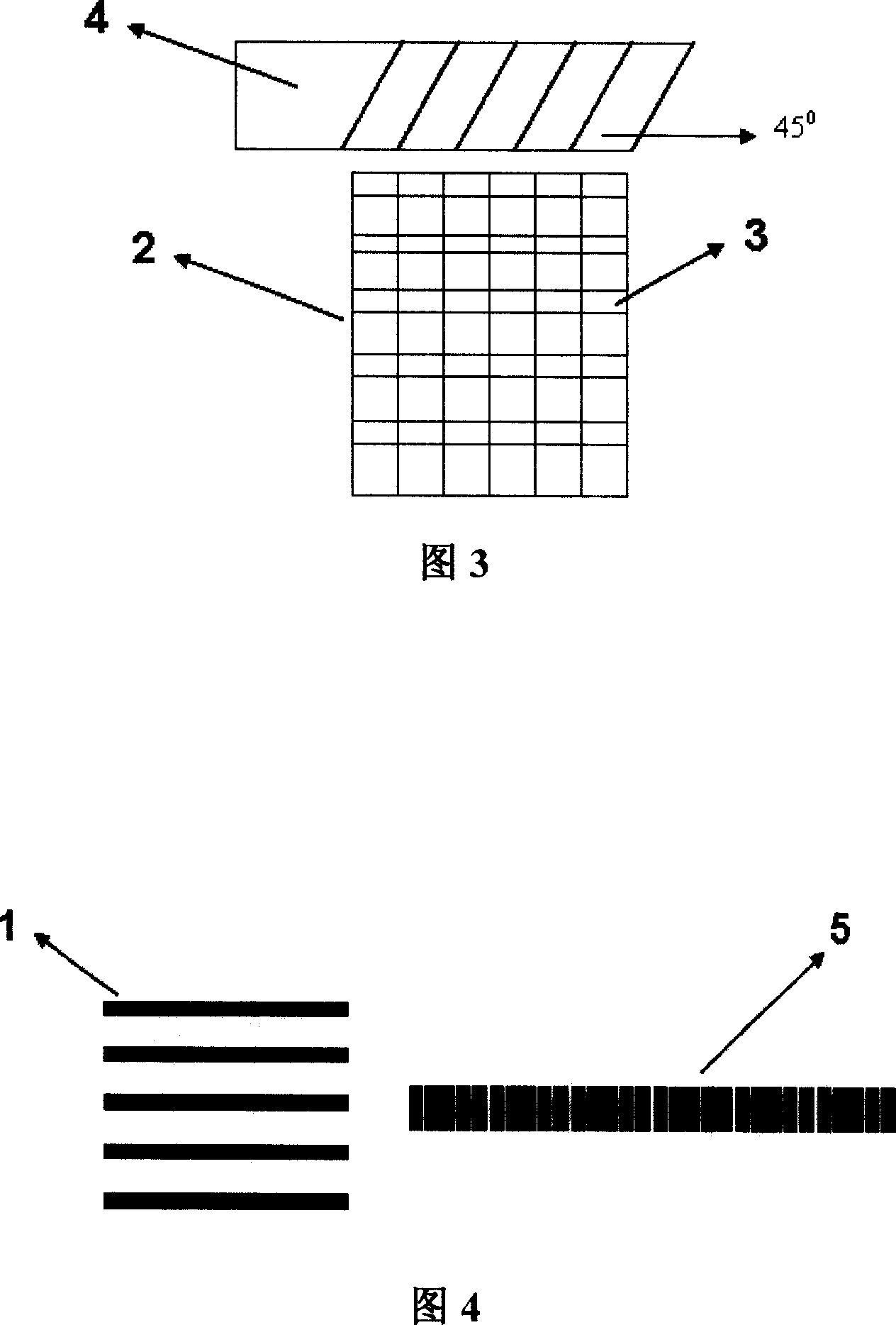
[0021] This embodiment will be described in detail below with reference to FIGS. 1 to 4 .

[0022] As shown in Figure 1, the laser diode stack is composed of 5 bars. After collimating the fast axis, the spot size 1 of each bar is about 10mm*0.8mm, that is, d5=10mm, d2=0.8mm, fast, The slow axis optical parameter product is about 2mm.mrad, 500mm.mrad. The thickness of the heat sink between the bars of the laser diode stack is d1=1.8mm, then the product of the fast and slow axis optical parameters of the laser diode stack is about 22mm.mrad and 500mm.mrad. The width d5 ​​along the slow axis direction of the stacked step mirror 2 and the height d6 along the fast axis direction are the same as the laser diode stack spot, ie d5=10mm, d6=5d2+4d1=11.2mm. The 6 reflectors in each row are staggered back and forth along the light transmission direction Z2, and the distance is equal to the sum of the spot sizes in the fast axis direction of the laser diode stack, that is, d3=5d2=4mm, an...


PUM


Abstract

A device for shaping light beam of heavy power laser diode stack is prepared as corresponding each rush bar of laser diode stack to each line reflector of stacked step reflector, setting the second step reflector above stacked step reflector, reflecting light spot being formed from each rush bar of laser diode stack and being collimated by fast shaft to fast shaft direction and driving said light spot to be n sections at slow shaft direction for eliminating dark region between rush bars off, reflecting n sections light beam by the second step reflector to turn light beam in 90 degree for realizing light beam-shaping.

Description

technical field [0001] The invention relates to a beam shaping device of a high-power laser diode stack, which belongs to the field of laser technology application. Background technique [0002] Due to the advantages of small size, light weight, and high electro-optical efficiency, semiconductor lasers have been more and more widely used. In particular, the fiber coupling of high-power semiconductor lasers is very useful for material processing, and will become a strong competition for lamp-pumped solid-state lasers. However, because the semiconductor laser is limited by its own structure, its beam quality is poor and its power density is low. At present, the commonly used multi-quantum well semiconductor lasers have light-emitting unit sizes of 100um-200um and 1um in the horizontal and vertical directions, resulting in a divergence angle of 36-40 degrees in the vertical direction, that is, the fast axis direction, and 8 degrees in the horizontal direction, that is, the slow...

Claims


Application Information

Patent Timeline
IPC IPC(8): G02F1/35G02B27/09G02B27/00H01S5/00
Inventor 王智勇康治军曹银花左铁钏
Owner SHANXI FEIHONG MICRO NANO PHOTOELECTRONICS SCI & TECH
Why Eureka
Try Eureka