
Method and device for controlling ion implantation

A technology of ion implantation and controller, which is applied in the manufacture of semiconductor/solid-state devices, discharge tubes, electrical components, etc. It can solve problems such as the difficulty of controlling stable ion implantation, and achieve the effects of easy determination, error reduction, and optimal control

Active Publication Date: 2007-07-18
BEIJING ZHONGKEXIN ELECTRONICS EQUIP
View PDF0 Cites 16 Cited by
  • Summary
  • Abstract
  • Description
  • Claims
  • Application Information

AI Technical Summary

Problems solved by technology

[0006] The present invention aims at the situation that it is difficult to control the stable implantation of ions when the system vacuum fluctuates in the prior art. To detect changes in vacuum pressure, so as to achieve the purpose of controlling ion implantation uniformity and dose accuracy

Method used


Image

  • Method and device for controlling ion implantation

Examples


Embodiment Construction

[0019] The present invention is described in further detail below in conjunction with specific embodiment:

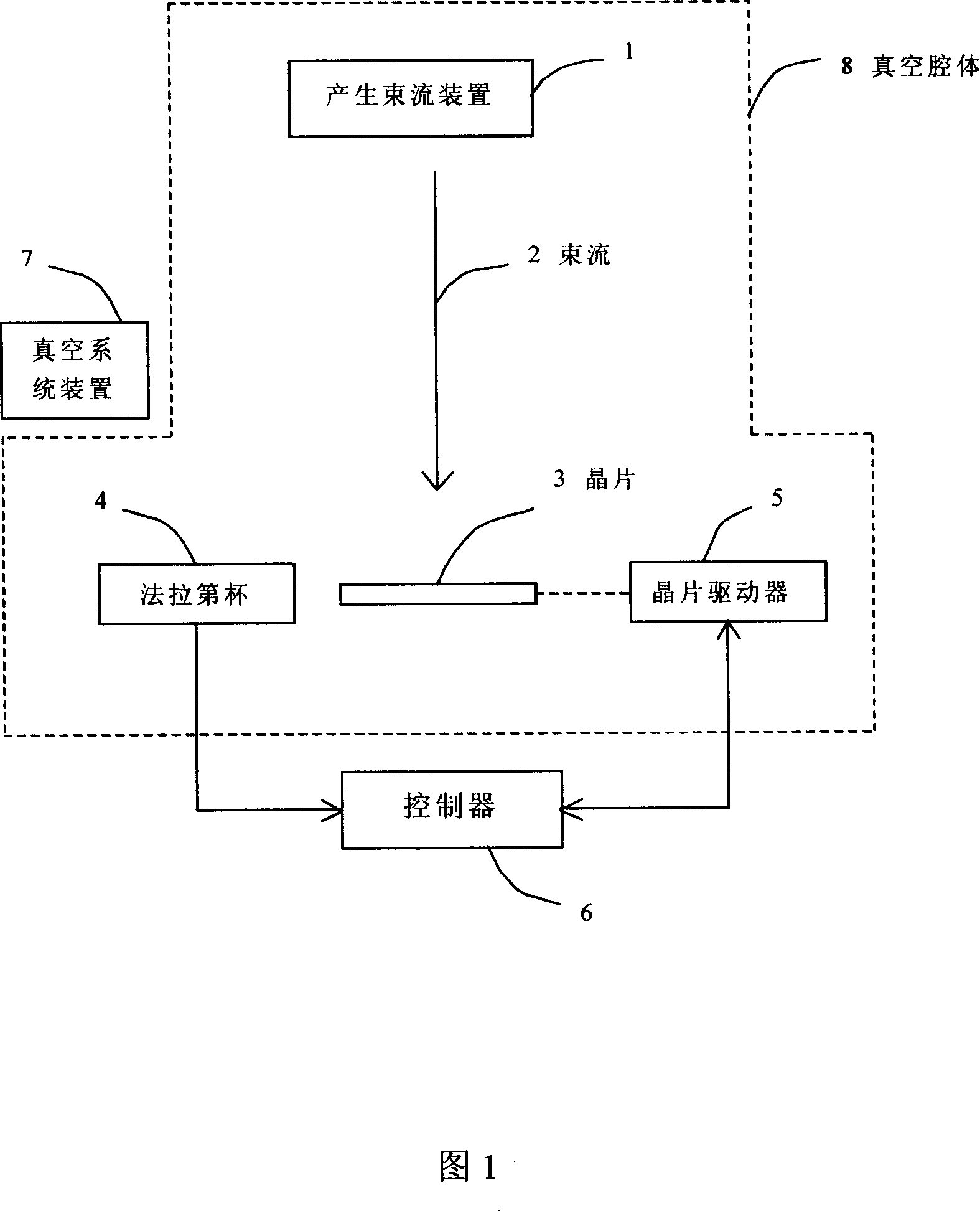
[0020] As shown in Figure 1, the device for controlling ion implantation includes generating a beam device 1, a wafer 3, a Faraday cup 4, a wafer driver 5, a controller 6, a vacuum system device 7, and a vacuum cavity 8, wherein the generating beam device 1 It is a linear beam 2 produced by ionizing the elements to be implanted through the ion source, and processed by magnetic field analysis and filtration; the beam 2 is vertically implanted into the wafer 3 after scanning, focusing, angle correction, energy acceleration, etc. ; The Faraday cup 4 is used to detect the value of the beam current 2, and outputs a signal reflecting the size of the beam current 2 to the controller 6; the controller 6 can be a general-purpose computer or a single-chip microcomputer circuit, as long as it has certain computing and storage capabilities , with simple input and output functions; ...


PUM


Abstract

A method for controlling ion implantation includes generating a linear beam by beam generator, injecting beam vertically into chip and using Faraday cup to detect beam value, outputting signal reflecting beam size to controller, carrying out communication between controller and chip actuator and driving chip to carry out scanning up and down by receiving parameter command sent by controller, transmitting beam in sealed vacuum cavity, utilizing vacuum unit to maintain vacuum environment of said cavity and controlling implantation dosage by controller. The device for realizing said method is also disclosed.

Description

technical field [0001] The invention relates to a semiconductor device manufacturing control system, in particular to a method and device for controlling ion implantation. Background technique [0002] The ion implanter is a device that changes the conductivity of the wafer by guiding impurities to be implanted into the semiconductor wafer. The depth and density uniformity of the impurity implantation directly determine the quality of the implanted wafer. When the ion beam hits the surface of the wafer, the photoresist or other materials coated on the wafer will be outgassed, volatilized or sputtered, which will cause vacuum fluctuations and affect the implantation dose and uniformity. For example, when the vacuum value rises due to outgassing and other reasons, the positive ions with single charge in the beam will collide with the residual atoms produced by outgassing and other reasons, so that part of the positive ions in the beam will be neutralized. It is then injected ...

Claims


Application Information

Patent Timeline
Patent Type & Authority Applications(China)
IPC IPC(8): H01L21/265H01J37/317
Inventor 谢均宇
Owner BEIJING ZHONGKEXIN ELECTRONICS EQUIP
Learn More