System for installing and adjusting adjustable reflection type optical object lens

An optical objective lens and reflective technology, which is applied in the field of adjustable reflective optical objective lens assembly and adjustment system, to achieve the effects of reducing mechanical deformation of the mirror surface, enhancing flexibility, and high precision

Inactive Publication Date: 2007-07-25
INST OF ELECTRICAL ENG CHINESE ACAD OF SCI
View PDF2 Cites 7 Cited by
  • Summary
  • Abstract
  • Description
  • Claims
  • Application Information

AI Technical Summary

Problems solved by technology

[0007] The technical problem to be solved by the present invention is to design an automatic objective lens assembly and adjustment mechanism, which can satisfy the multi-degree-of-freedom automatic leveling and focusing function of the photolithography system, and has high positioning accuracy and stability. Minimal mechanical deformation of the mirror surface

Method used


Image

  • System for installing and adjusting adjustable reflection type optical object lens
  • System for installing and adjusting adjustable reflection type optical object lens
  • System for installing and adjusting adjustable reflection type optical object lens

Examples


Embodiment Construction

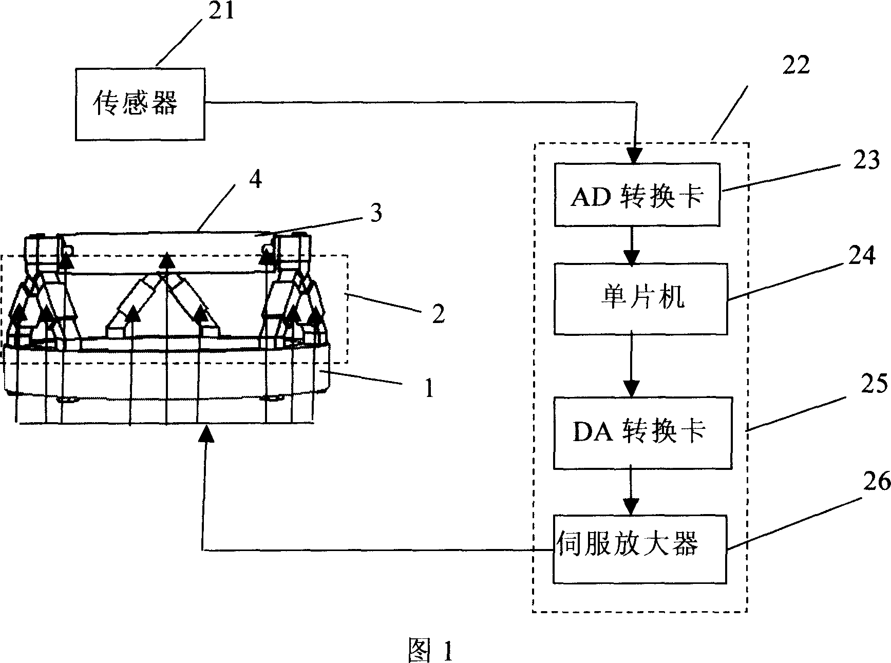
[0020] The objective lens assembly and adjustment system of the present invention comprises a base 1 , an adjuster assembly 2 , an objective lens 3 , a sensor 21 , a controller 22 , an AD conversion card 23 , a single-chip microcomputer 24 , a D / A conversion card 25 and a servo amplifier 26 .

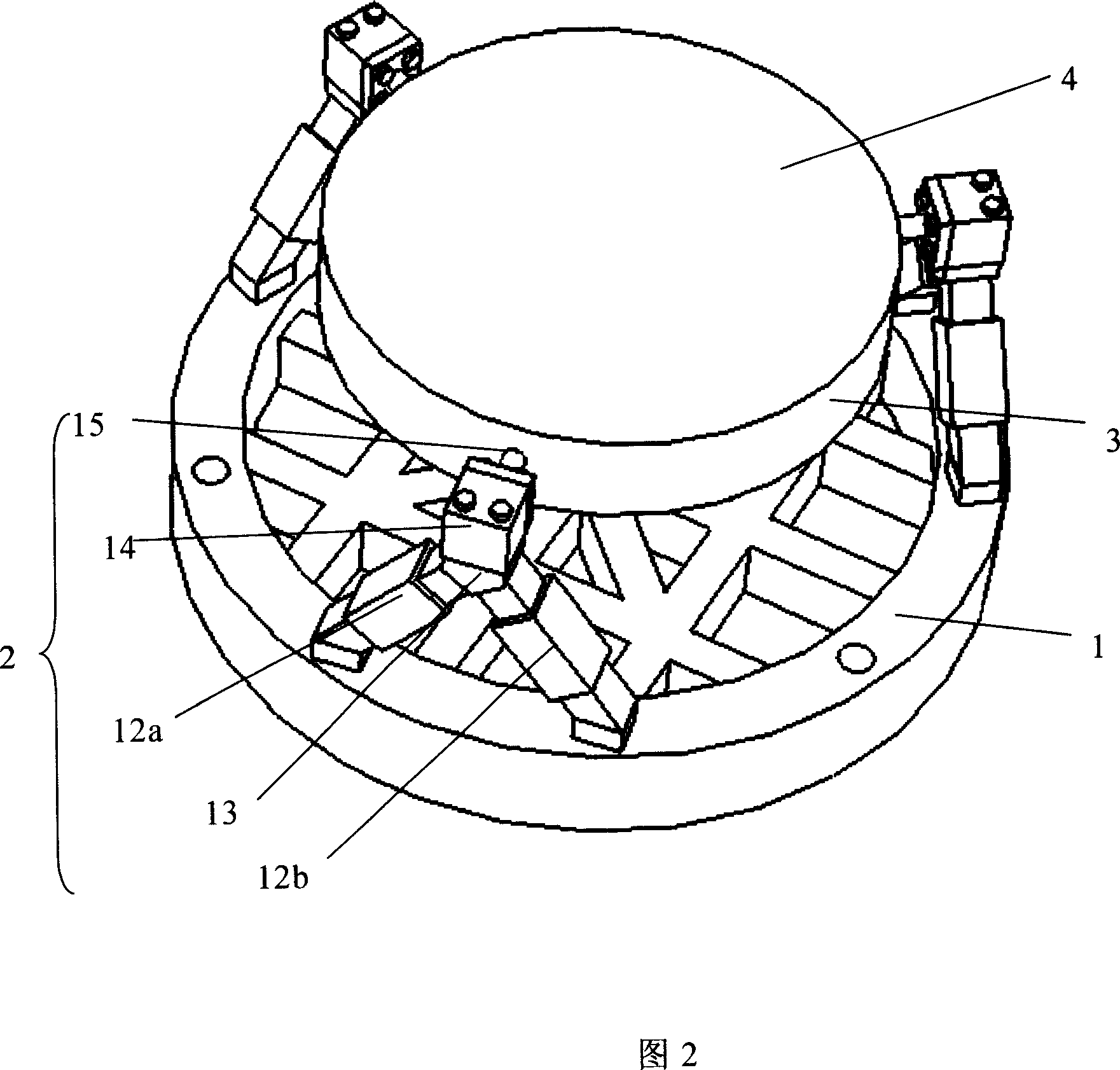
[0021] As shown in Fig. 1 and Fig. 2, the base 1 is located at the bottom end, which is the fixed part of the whole assembly and adjustment mechanism. Three sets of regulator assemblies 2 are evenly distributed on the base 1 along the circumference at intervals of 120°. Each set of adjuster assemblies 2 includes two adjusting rods 12a, 12b and a radial adjuster 15, the lower ends of the adjusting rods 12a and 12b are fixedly connected to the base 1 by bolts, and the upper ends of the two adjusting rods 12a and 12b are fixedly connected to the connector 13 on. The latter is bolted to the fixing plate 14 and connected to the radial adjuster 15 . The adjusting rods 12a and 12b are retrac...


PUM


Abstract

A regulation system of optical objective lens in adjustable reflection type is prepared for sending analog signal from transducer to A/D conversion card then to monolithic computer, calculating actual position and dip angle of objective lens by said computer, calculating out parameter to be regulated by regulation system component by comparing position and dip angle of objective lens with that of object, sending said parameter to servo amplifier then to regulation system component to make said component generate relevant linear movement to drive objective lens to required position.

Description

technical field [0001] The invention relates to an adjustable reflective optical objective lens adjustment system, in particular to an objective lens adjustment system for a projection photolithography machine. Background technique [0002] The lithography quality of a projection lithography machine mainly depends on the quality of the optical system, and the quality of the optical system is determined by the mirror surface processing error and the assembly error. For projection lithography machines, the quality of the optical system is reflected by wave aberration. The wave aberration of ordinary 193nm wavelength lithography machines is 2-3nm, while the wave aberration of extreme ultraviolet projection lithography machines should be controlled at 1nm within. Wave aberration not only depends on the high precision of the mirror, but also depends on its installation error, as well as the mirror deformation caused by mechanical adjustment. Therefore, the designed objective le...

Claims


Application Information

Patent Timeline
Patent Type & Authority Applications(China)
IPC IPC(8): G03F7/20G02B26/08
Inventor 朱涛李艳秋
Owner INST OF ELECTRICAL ENG CHINESE ACAD OF SCI
Why Eureka
Try Eureka