Output voltage state indicator for power source chip

A technology of output voltage and state indication, applied in the field of power chips, which can solve problems such as increased chip power consumption, increased bias current, and increased chip area, and achieves the effects of reduced chip power consumption, simple structure, and easy implementation

Inactive Publication Date: 2007-07-25
HUAZHONG UNIV OF SCI & TECH
View PDF0 Cites 17 Cited by
  • Summary
  • Abstract
  • Description
  • Claims
  • Application Information

AI Technical Summary

Problems solved by technology

In the patent document "Voltage Detection Circuit" (application number: 99N6974), the voltage detection circuit designed can realize the detection of the high and low thresholds of the same voltage, that is, it has the function of window detection, but it still uses two comparators
Due to the use of two comparators, the area of ​​the chip will inevitably increase, the number of devices will also increase, the bias current will also increase, and the power consumption of the chip will also increase.

Method used


Image

  • Output voltage state indicator for power source chip
  • Output voltage state indicator for power source chip
  • Output voltage state indicator for power source chip

Examples


Embodiment Construction

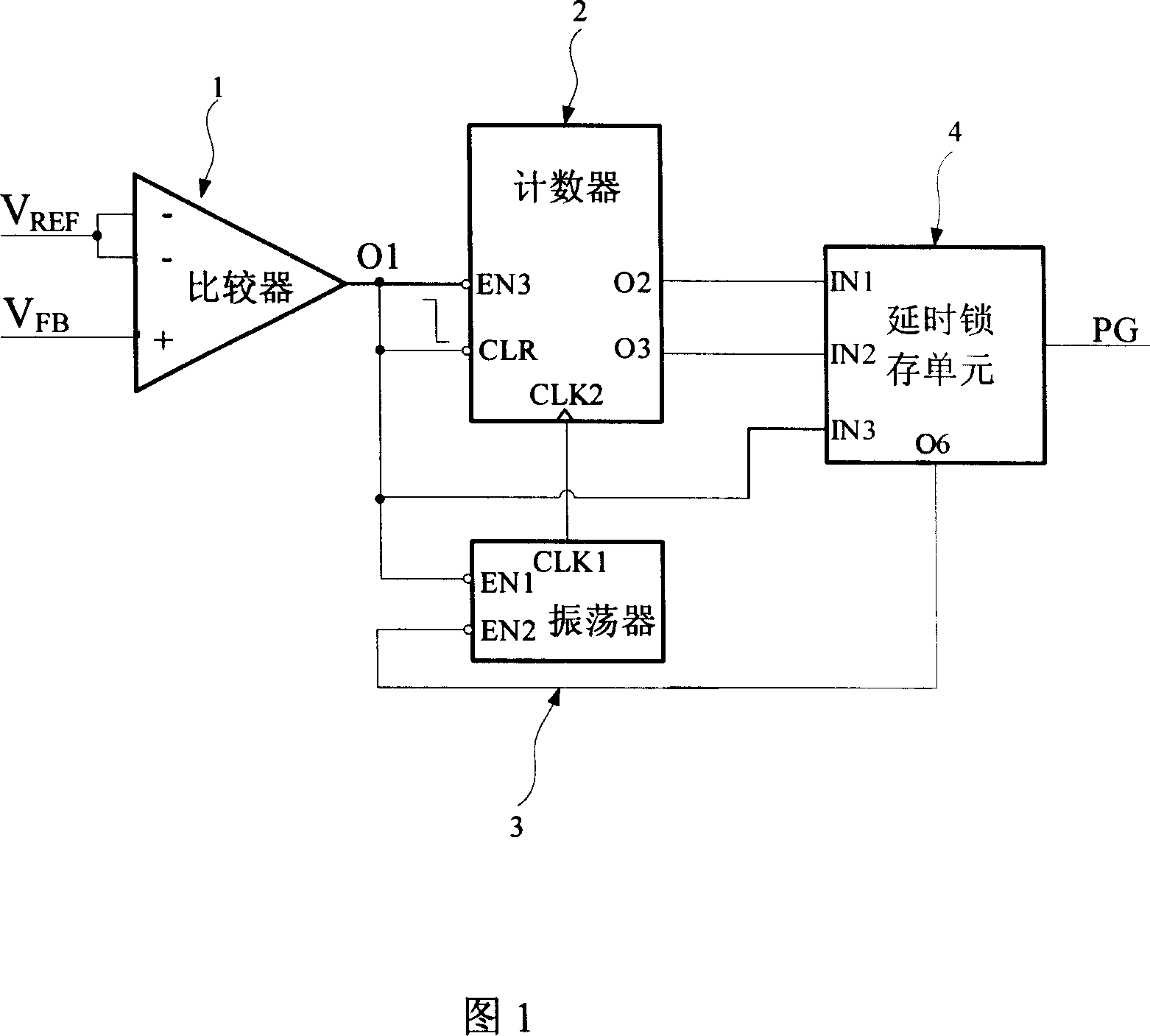
[0014] As shown in FIG. 1 , the output voltage indicating circuit of the present invention includes: a dual-threshold comparator 1 , a counter 2 , an oscillator 3 , and a delay latch unit 4 . The final output signal PG (Power Good) is used to indicate whether the output voltage is working within the set normal range.

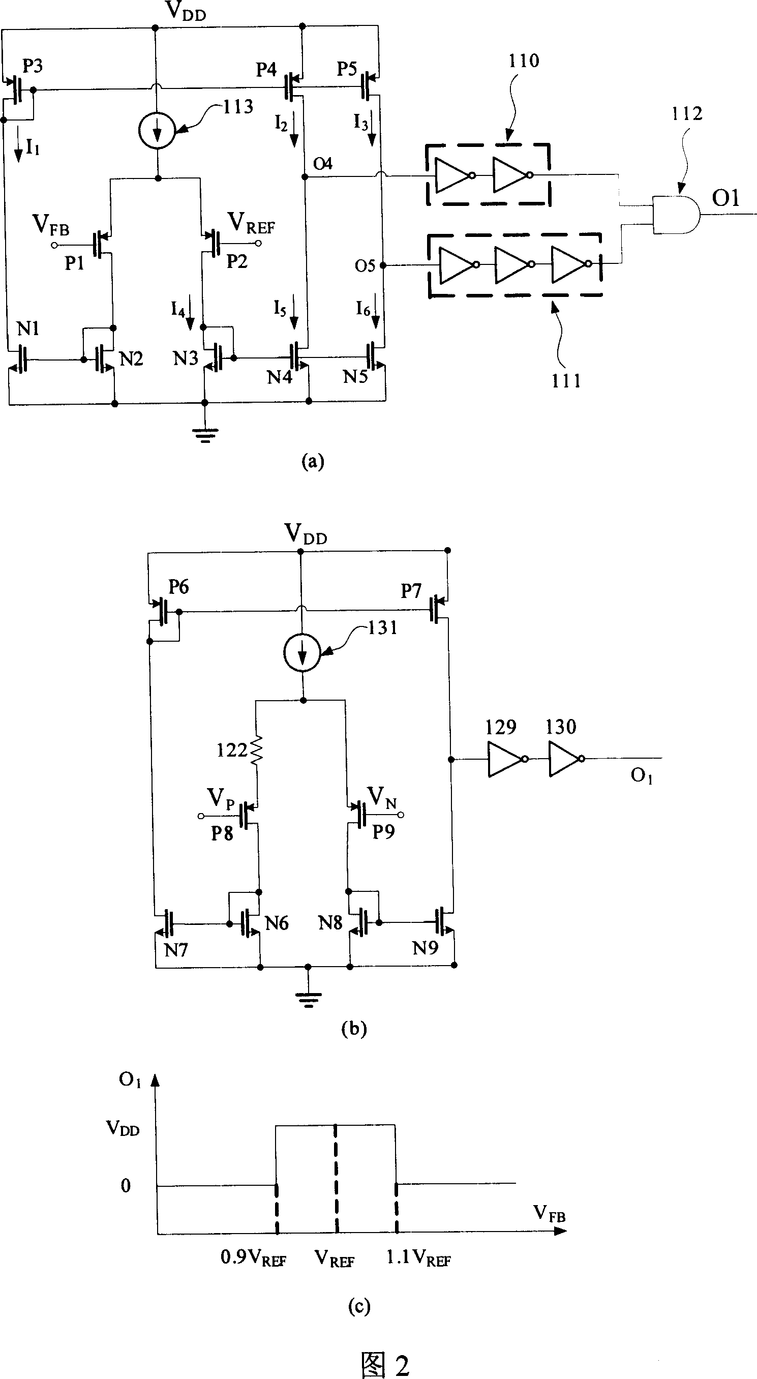
[0015] There are 3 input terminals in the dual-threshold comparator 1, and the two negative input terminals are connected to the reference voltage V generated inside the chip. REF , the threshold voltages corresponding to these two negative terminals are V TH - and V TH + . The positive input terminal is connected to the feedback signal V of the output voltage of the power chip FB , O 1 is the comparator output signal. When the output voltage has V TH - OUT TH + when V O1 = 1, otherwise, V O1 =0.

[0016] The counter 2 is N-bit and has a clearing terminal, and has three input terminals: an enabling terminal EN3, a clearing terminal CLR and a clock s...


PUM


Abstract

The indication circuit includes comparator with double threshold values, counter, oscillator and time delay latch unit. The comparator is in use for restricting range of output voltage VOUT of switching power supply chip. The counter always outputs a pair of opposite signal. The oscillator is in use for the counter to generate periodic signal of square wave. The time delay latch unit provides following functions: detecting time when output voltage is in abnormal condition; if error is corrected within a relaxation time, then recovering the output voltage to normal range; thus, the circuit outputs signal to indicate normal voltage; if error is not corrected within a relaxation time, then the circuit outputs signal to indicate abnormal voltage for chips in subsequent chips to take corresponding protective measures. Advantages are: saving area of chip, reducing power consumption of chip, simple structure, and easy of implementation.

Description

technical field [0001] The invention belongs to the field of power chips, in particular to an output voltage state indicating circuit for a power chip. Background technique [0002] In recent years, the integrated circuit (Integrated Circuits) industry has developed rapidly, and the digital signal chip (Digital Signal Process) and digital-analog mixed signal chip (MixedSignal IC) are the backbone of the development. In this context, switching power supply chips that provide power for other chips have also been more widely used. The switching power supply chip uses other external power supply sources (such as lithium batteries, AC-DC transformers for commercial power) as the input power supply, and obtains a stable output voltage through the conversion of the chip's internal circuit and peripheral energy storage devices. If the output voltage is higher than the input voltage, we call it a boost chip; if the output voltage is lower than the input voltage, we call it a step-do...

Claims


Application Information

Patent Timeline
Patent Type & Authority Applications(China)
IPC IPC(8): H02H7/20G01R19/165
Inventor 邹雪城张科峰邹志革王潇田欢尹璐骞海荣韩俊峰
Owner HUAZHONG UNIV OF SCI & TECH
Why Eureka
Try Eureka