Water energy-storage system with multi flume tanks and using method thereof

一种贮水槽、水蓄能的技术,应用在水蓄能系统,多贮水槽水蓄能系统领域,能够解决浪费贮存空间、降低蓄能效率、成本增加等问题,达到分层发生紊乱的机会减小、充能或释能同步、蓄能效率提高的效果

Active Publication Date: 2007-08-01
CHANGZHOU RUICHENG IOT TECH CO LTD
View PDF0 Cites 16 Cited by
  • Summary
  • Abstract
  • Description
  • Claims
  • Application Information

AI Technical Summary

Problems solved by technology

There are two disadvantages in such operation: 1) When switching the water storage tank, frequent operations are required, which is prone to errors; 2) Compared with a single water storage tank, the power of the cold source or heat source is generally too large, and the working flow is too large at full load, making the layout The water effect and energy storage efficiency become worse. If the power is reduced for this reason, the efficiency of the cold (heat) source will be reduced.
There are three disadvantages in such operation: 1) The flow rate in series may be too large for each water storage tank, making the water distribution effect relatively poor; 2) The water flow repeatedly passes through the water distributors of each water storage tank, which greatly increases the chance of mixing hot and cold water. Significantly reduce the energy storage efficiency; 3) If each water storage tank in series is an open system, the water flow in each water storage tank must be driven by the water level difference. The direction of the water flow is exactly opposite to that of the two working conditions of cooling (heating), and there are completely opposite requirements for the water level gradient of the water storage tank. The design and installation of water heaters are more difficult, and part of the storage space is wasted; if each series water storage tank is a closed system, each tank must adopt a pressure-bearing design, which greatly increases the cost
[0011] 2. During the parallel synchronous operation of the energy storage tanks, if the energy storage tanks cannot complete the charging and discharging strictly synchronously, the volume utilization rate of the storage tanks will be reduced
[0012] The above technical difficulties have not been effectively solved in the existing technology, so the method of multi-water storage tanks connected in parallel and synchronously charging and releasing energy has not been applied

Method used


Image

  • Water energy-storage system with multi flume tanks and using method thereof

Examples


Embodiment Construction

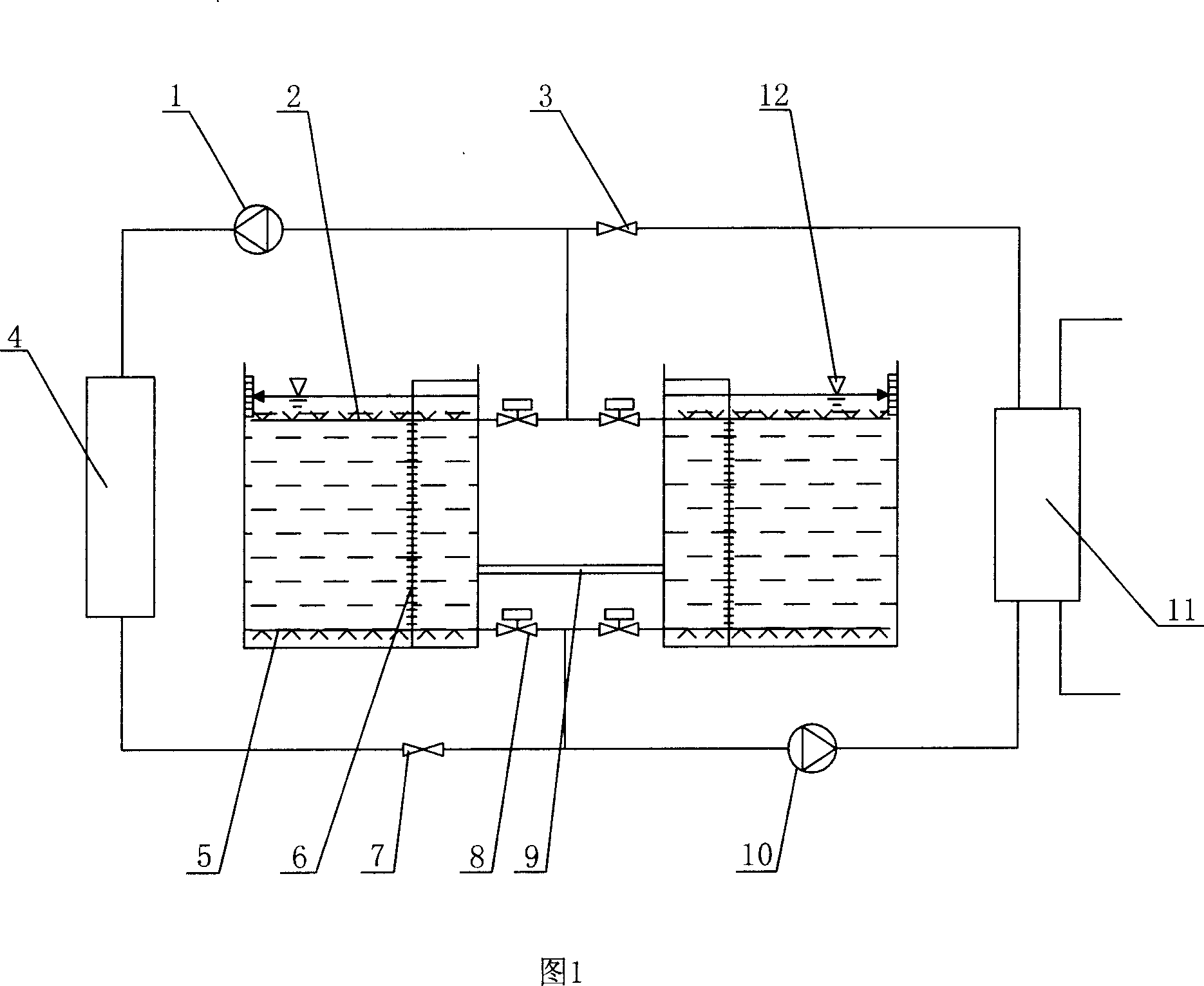
[0029] The embodiment shown in Figure 1, the water cold storage air-conditioning system has two water storage tanks, and the upper water distributor 2, the lower water distributor 5, the water level sensor 12 and the temperature sensor 6 are respectively arranged in the two water storage tanks, and the temperature sensor 6 There are a plurality of them, which are evenly distributed in each water layer of the water storage tank from top to bottom. The upper water distributors 2 of the two water storage tanks are connected in parallel and divided into two circuits, one of which is connected to the chiller 4 and the other is connected to the heat exchanger 11; the lower water distributors 5 of the two water storage tanks are connected in parallel and then divided into two circuits, one of which is connected to the chiller 4. The other road is connected to the heat exchanger 11; the water inlet and outlet pipes of the chiller 4 are respectively provided with a charge cooling pump 1...


PUM


Abstract

The invention discloses a multi-water-groove energy-accumulating system and relative operation. The invention comprises at least two water grooves, cold (hot) water machines and heat exchanger; the water grooves contain upper and lower water distributors which are parallel connected and connected to the cold (hot) water machine and the heat exchanger; the tubes of upper and lower water distributors are arranged with adjusting valves; the water inlet tube of cold (hot) water machine is arranged with discharge pump; the water inlet tube of heat exchanger is arranged with a release pump; the water grooves contain temperature sensor. The invention parallel connects several water grooves and accumulates energy together, without switching the water grooves frequently. The cold (hot) water machine can operate at full load with high efficiency; the flux of each water groove is small. The invention only needs to distribute water one time, and the position of water groove is not limited strictly to release energy synchronously.

Description

technical field [0001] The invention relates to an energy-saving system using water energy storage, in particular to a water energy storage system with multiple water storage tanks, and also relates to a method for using the water energy storage system with multiple water storage tanks. Background technique [0002] With the continuous improvement of people's living standards, the use of air-conditioning technology that requires heat sources in winter and cold sources in summer is becoming more and more common. Under normal circumstances, the power load of the air conditioning system is heavy during the day and light at night, and it competes with other loads of the power grid for peaks and valleys, which is one of the main factors causing the peak-valley load difference of the power grid. In order to ensure the safe, reasonable and economical operation of the power grid, encourage users to adjust loads, and realize "shifting peaks and filling valleys", the country implement...

Claims


Application Information

Patent Timeline
Patent Type & Authority Applications(China)
IPC IPC(8): F25D1/02F24F5/00
CPCY02E60/147F28D20/0039F28D20/0034Y02E60/142F24F5/0017Y02E60/14
Inventor 刘洪江源泉侯张炜
Owner CHANGZHOU RUICHENG IOT TECH CO LTD
Why Eureka
Try Eureka