Efficient anti-pollution cation (anion) ion exchanger

A technology of ion exchangers and exchangers, applied in the field of ion exchangers, can solve problems such as no good limit function of branch pipes, easy damage of water distribution pipes and branch pipes, no good disassembly and assembly operations, etc., to achieve convenient management and avoid branch pipes Rotation, good operation effect

Active Publication Date: 2021-09-17
LIANYUNGANG ZHENGHANG ELECTRIC ENERGY CONSERVATION TECH
View PDF6 Cites 0 Cited by
  • Summary
  • Abstract
  • Description
  • Claims
  • Application Information

AI Technical Summary

Problems solved by technology

[0004] This kind of ion exchanger needs water distribution during use. After a long time of use, the water distribution pipe and the branch pipe are easily damaged or blocked. It needs to be disassembled and maintained. There is no good disassembly operation, and there is no good restriction on the branch pipe. Potential effect, there are disadvantages in use, based on this, the present invention designs a high-efficiency anti-pollution cation (anion) ion exchanger to solve the above problems

Method used


Image

  • Efficient anti-pollution cation (anion) ion exchanger
  • Efficient anti-pollution cation (anion) ion exchanger
  • Efficient anti-pollution cation (anion) ion exchanger

Examples


Embodiment 1

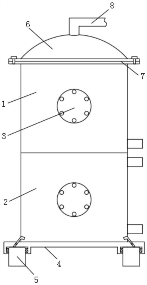
[0030] Embodiment 1: including the first exchanger 1 and the second exchanger 2, the first exchanger 1 is located at the upper end of the second exchanger 2, and the front ends of the first exchanger 1 and the second exchanger 2 are provided with through-hole covers Plate 3, the upper end surface of the first exchanger 1 is provided with a top cover 6, and the inner upper end of the first exchanger 1 is provided with a water distribution mechanism;

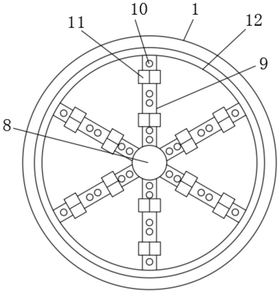
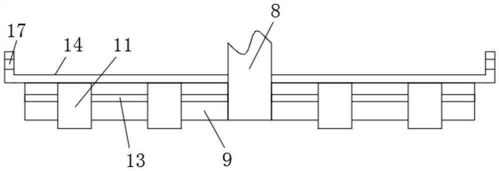
[0031] The water distribution mechanism includes a water distribution pipe 8, a fixed ring 12, a fixed rod 14, a branch pipe 9, a limit hoop 11, an elastic hinge 16 and a screw hole 17. The water distribution pipe 8 runs through the inside of the top cover 6 and extends to the first exchange Inside the device 1, there are several branch pipes 9, one end of several branch pipes 9 is connected to the water distribution pipe 8, the fixed rod 14 is fixedly connected between the fixed ring 12 and the water distribution pipe 8, and the l...

Embodiment 2

[0032] Embodiment 2: including the first exchanger 1 and the second exchanger 2, the first exchanger 1 is located at the upper end of the second exchanger 2, and the front ends of the first exchanger 1 and the second exchanger 2 are provided with through-hole covers Plate 3, the upper end surface of the first exchanger 1 is provided with a top cover 6;

[0033] A limiting mechanism is arranged between the branch pipe 9 and the limiting hoop 11. The limiting mechanism includes a limiting bar 13 and a limiting groove 15. The limiting groove 15 is set on the inner side of the limiting hoop 11, and the limiting bar 13 is fixedly connected. On both sides of the outer surface of the branch pipe 9 , the positions between the limiting strips 13 and the limiting grooves 15 correspond to each other.

Embodiment 3

[0034] Embodiment 3: including the first exchanger 1 and the second exchanger 2, the first exchanger 1 is located at the upper end of the second exchanger 2, and the front ends of the first exchanger 1 and the second exchanger 2 are provided with through-hole covers Plate 3, the upper end surface of the first exchanger 1 is provided with a top cover 6;

[0035] The lower end surface of the second exchanger 2 is provided with a base 4, and the corner positions of the lower end surface of the base 4 are all provided with supporting feet 5, and a connecting mechanism is provided between the base 4 and the second exchanger 2, and the connecting mechanism includes a buckle bar 18, Elastic hinge 2 19, spring 20 and slot, the slot is opened on the outer surface of the second exchanger 2 near the position of the leg 5, the buckle bar 18 is movably connected to the inside of the base 4 through the elastic hinge 2 19, and the spring 20 is sleeved on the The outside of the leg 5, and the...


PUM


Abstract

The invention discloses an efficient anti-pollution cation (anion) ion exchanger in the technical field of ion exchangers, which comprises a first exchanger and a second exchanger, the first exchanger is positioned at the upper end of the second exchanger, through hole cover plates are arranged at the front ends of the first exchanger and the second exchanger, and a top cover is arranged on the upper end surface of the first exchanger. A water distribution mechanism is arranged at the upper end in the first exchanger; the water distribution mechanism comprises a water distribution pipe, a fixing ring, a fixing rod, a plurality of branch pipes, a limiting hoop, a first elastic hinge and a screw hole, the water distribution pipe penetrates through the interior of the top cover and extends into the first exchanger, one end of each branch pipe is connected with the water distribution pipe, and the fixing rod is fixedly connected between the fixing ring and the water distribution pipe. The water distribution holes are formed in the lower ends of the branch pipes, so that the branch pipes are prevented from rotating, the water distribution holes can be always kept downward, a better limiting effect is achieved, subsequent disassembly can be performed, and workers can conveniently manage the branch pipes.

Description

technical field [0001] The invention relates to the technical field of ion exchangers, in particular to a high-efficiency anti-pollution positive (negative) ion exchanger. Background technique [0002] Ion exchangers are divided into sodium ion exchangers, anion-yang beds, mixed beds and other types. As a power auxiliary machine, ion exchangers can effectively treat waste water discharge and are widely used in the treatment of existing social sewage. Ion exchange The column (device) shell is generally made of hard polyvinyl chloride, hard polyvinyl chloride composite FRP, plexiglass, plexiglass composite transparent FRP, steel-lined rubber, stainless steel-lined rubber and other materials. [0003] For example, Chinese Patent Application No. CN201721282642.0 is a flat-bottomed anion-and-cation exchanger for chemical water system equipment. The specific content is: the first exchanger, the second exchanger, the base, the first flat-bottomed head, and the second flat-bottomed ...

Claims


Application Information

Patent Timeline
IPC IPC(8): C02F1/42
CPCC02F1/42C02F2001/422C02F2001/425C02F2301/08C02F2303/14
Inventor 何乃昌何星
Owner LIANYUNGANG ZHENGHANG ELECTRIC ENERGY CONSERVATION TECH
Why Eureka
Try Eureka