Pressurization trace quantity helix powder feeding equipment

A screw and powder feeding technology, applied in the directions of loading/unloading, packaging, gear transmission, etc., can solve the problems of aggravated bearing and screw shaft wear, material accumulation and unsmooth feeding, pulverized coal escaping, etc., to avoid accumulation. , Smooth powder output, ensure the effect of normal rotation

A screw and powder feeding technology, applied in the directions of loading/unloading, packaging, gear transmission, etc., can solve the problems of aggravated bearing and screw shaft wear, material accumulation and unsmooth feeding, pulverized coal escaping, etc., to avoid accumulation. , Smooth powder output, ensure the effect of normal rotation

CN101012031AInactive Publication Date: 2007-08-08UNIV OF SCI & TECH OF CHINA

Image

  • Pressurization trace quantity helix powder feeding equipment
  • Pressurization trace quantity helix powder feeding equipment

Examples


Embodiment Construction

[0018] The specific implementation of the present invention using a pressurized micro-volume screw powder feeder will be further described below in conjunction with the accompanying drawings.

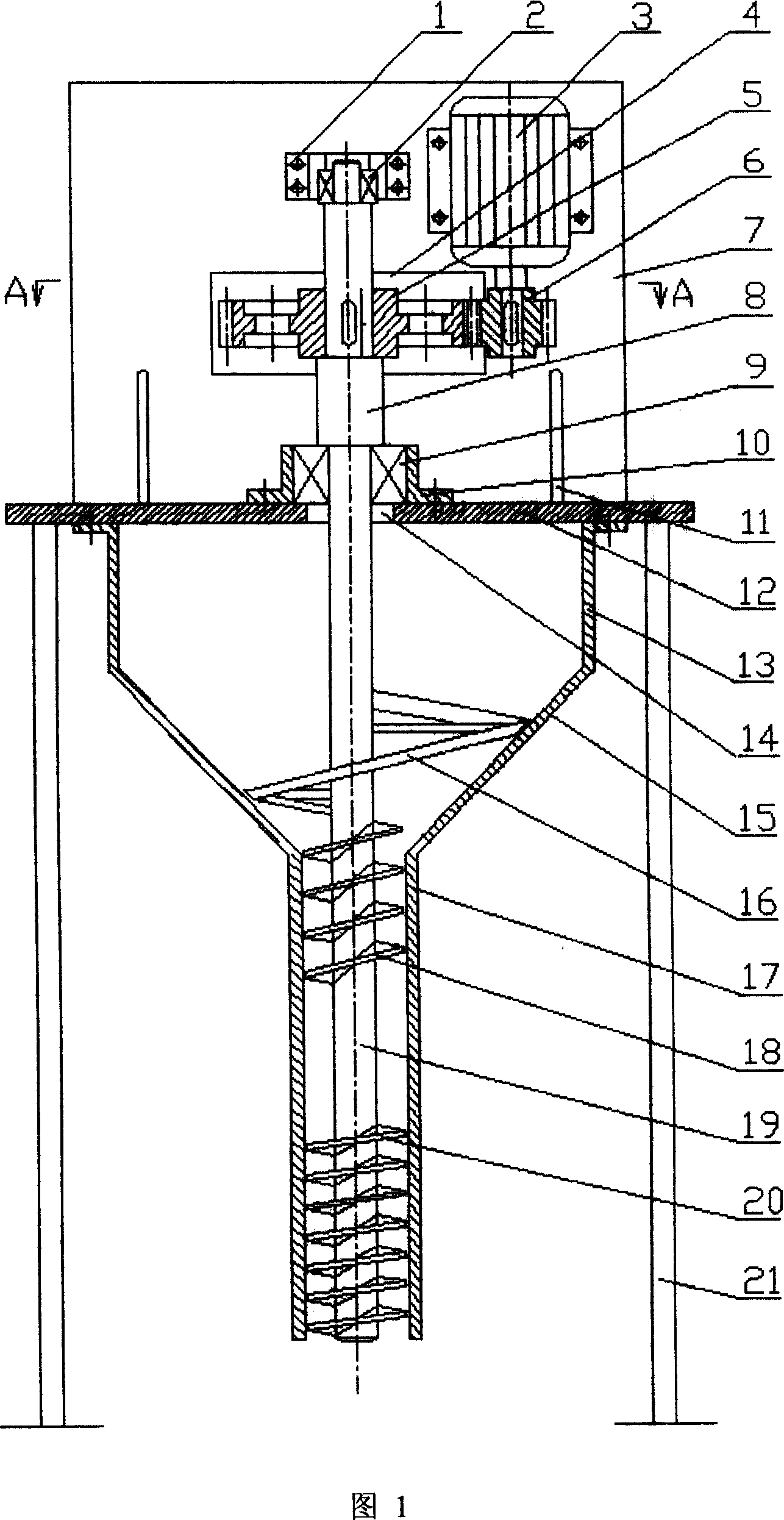
[0019] The pressurized micro screw powder feeder of this embodiment includes a motor 3, a large gear 5 and a pinion 6 meshing with each other, a screw shaft 8, an agitator 16, an upper helical blade 18 and a lower helical blade 20, a cylindrical section hopper 13 and a cone Section hopper 15, discharge pipe 17, support table 12. The whole machine is placed vertically.

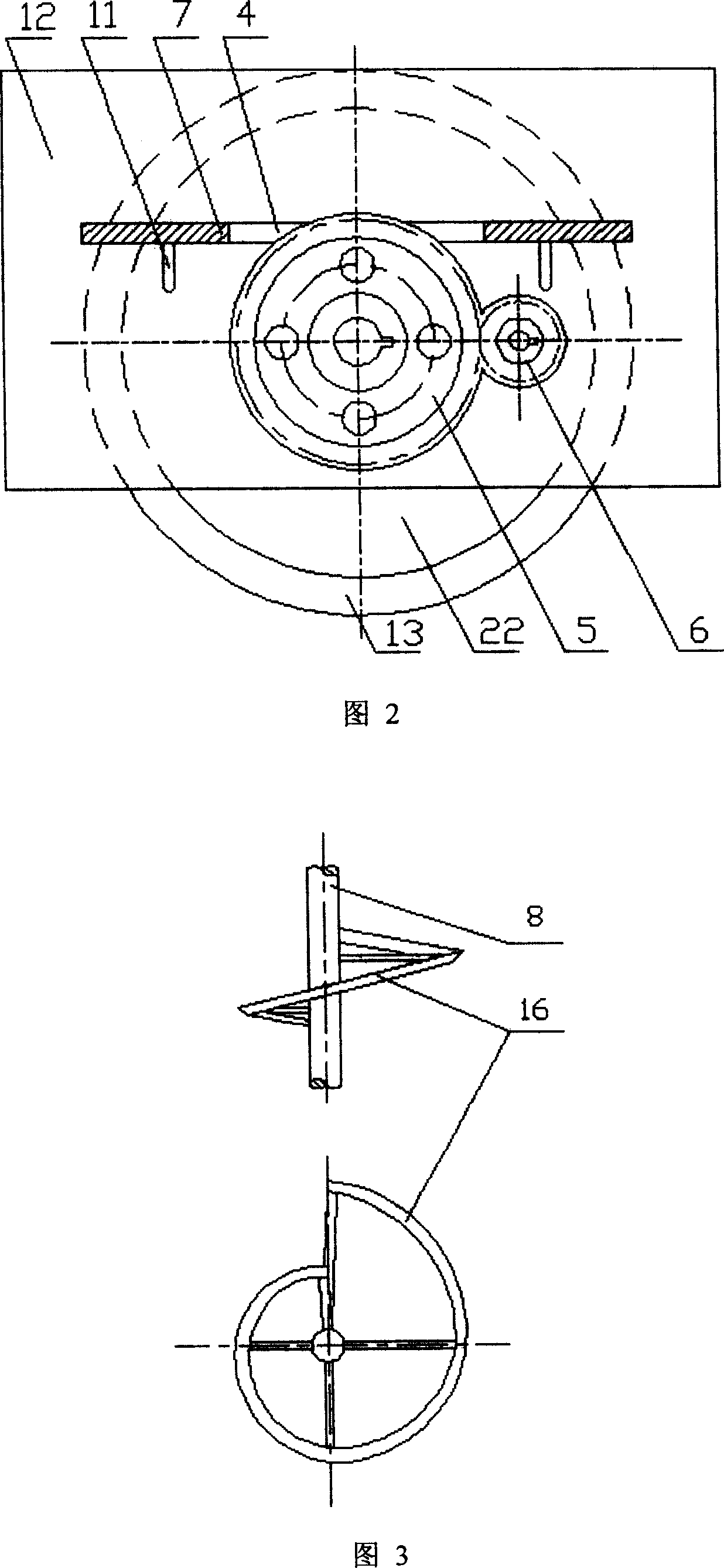
[0020] Fig. 1 shows a schematic structural view of a pressurized micro-volume spiral powder feeder, Fig. 2 is a sectional view of A-A of Fig. 1, and Fig. 3 is a schematic structural view of a gradually expanding ribbon agitator 16.

[0021] The vertical plate 7 is vertically fixed on the support table 12, and the two ends of the two inclined support rods 11 are respectively welded on the vertical plate 7 and the support...


PUM


Abstract

The pressurized micro spiral powder feeder drives the screw shaft through drive mechanism by generators, hopper and material outlet pipe integrated under the lower surface of the support platform, featuring in its being load bore by support platform and positioned by the middle up shaft bearing, vertically going through the insert hopper of the round hole, the lower end sticking to the material output pipe in arm shape, blender at the screw shaft of the corresponding position of the conical sectional hopper, intermittently fixing two sections spiral vanes with different pitches, lower spiral vane pitch smaller than the pitch of the upper spiral vane, leaving a section of emptiness between the spiral shaft of the spiral vanes. It is simple and compact in structure, adjustable in feeding quantity, even and stable in pressurized transportation.

Description

Technical field: [0001] The invention belongs to the technical field of material conveying equipment, in particular to a micro-volume screw powder feeder for pressurizing and conveying viscous powdery materials. Background technique: [0002] "Modern Coal Chemical Technology Handbook" (Edited by He Yongde, Beijing: Chemical Industry Press, 2003, 11, page 516 and page 527) mentions that the key of dry gasification technology lies in the pressurized feed of pulverized coal. The foreign advanced technology adopts a semi-continuous coal feeding process in which two conveying lines composed of a feeder and an air lock mechanism are switched and alternated, and pulverized coal is continuously fed under indirect boost and pressure. This technology has complex equipment and high process requirements, and is suitable for pressurized transportation of pulverized coal with large flow rate (above 1t / h), but it cannot be applied to pressurized gasifiers with small amount of pulverized co...

Claims


Application Information

Patent Timeline
08 Aug 2007
Publication
CN101012031A
IPC
B65G65/46; B65G33/14; B65G33/26; B65G33/32; B65G33/34; F16H1/06; F16H7/02
Inventors
唐志国; ζž—ε…Άι’Š