Laser embroidery integrated machine and processing method

An all-in-one machine and laser technology, which is applied in the field of embroidery equipment and textile processing equipment, can solve the problems of long mold production cycle, high cost, and waste products, and achieve the effect of saving loading and unloading time and labor costs

Inactive Publication Date: 2007-08-08
WUHAN GOLDEN LASER
View PDF0 Cites 11 Cited by
  • Summary
  • Abstract
  • Description
  • Claims
  • Application Information

AI Technical Summary

Problems solved by technology

In the traditional processing technology, the defect of the die cutting method used for cutting before embroidery is that it is easy to produce fabric fringe, and the processing accuracy is limited by the die die, it is difficult to process heterogeneous patterns, the production cycle of the die die is long, the cost is high, and labor Poor registration and waste of time, thus inhibiting the development of appl

Method used


Image

  • Laser embroidery integrated machine and processing method
  • Laser embroidery integrated machine and processing method
  • Laser embroidery integrated machine and processing method

Examples


Embodiment 1

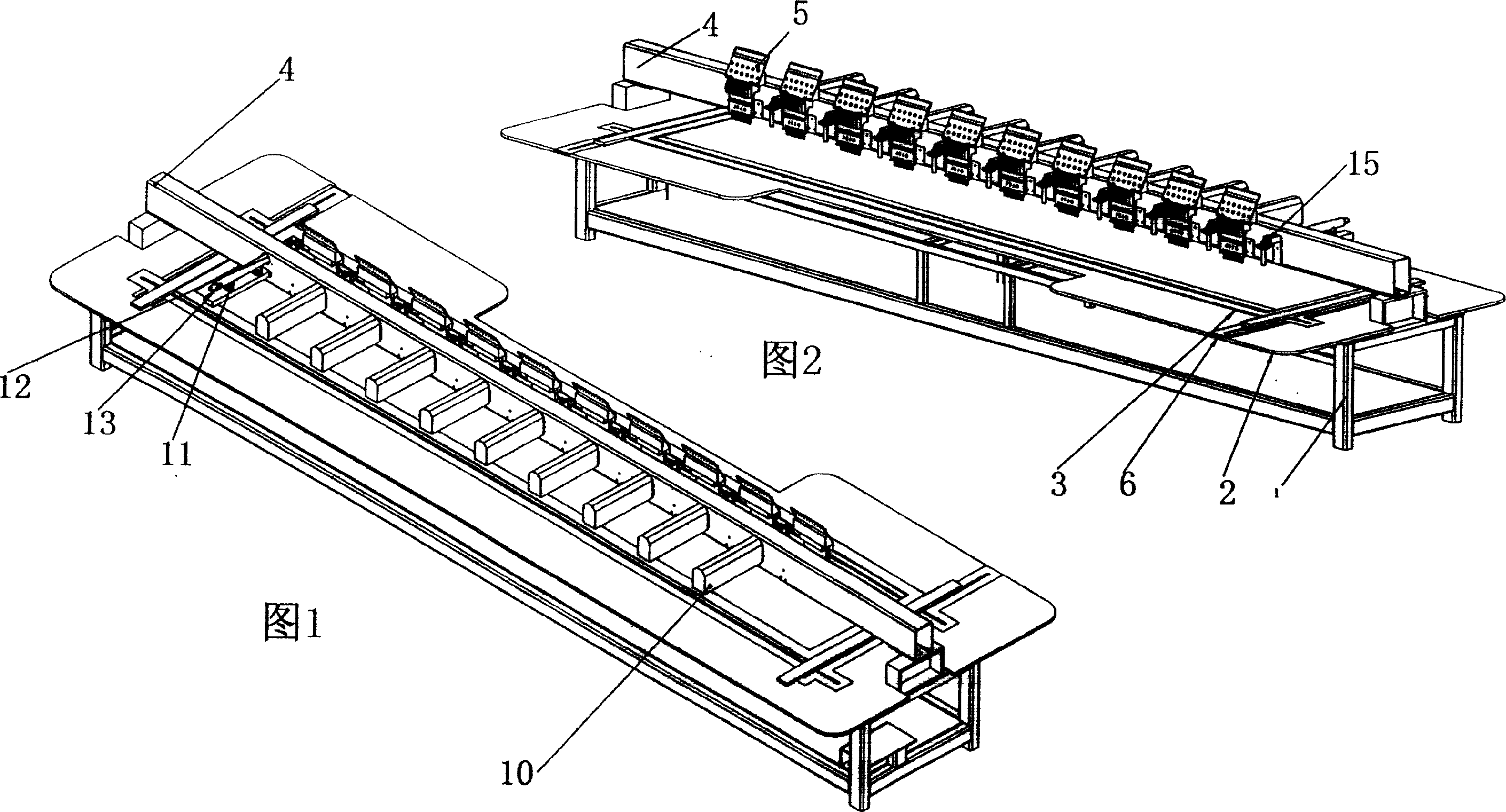
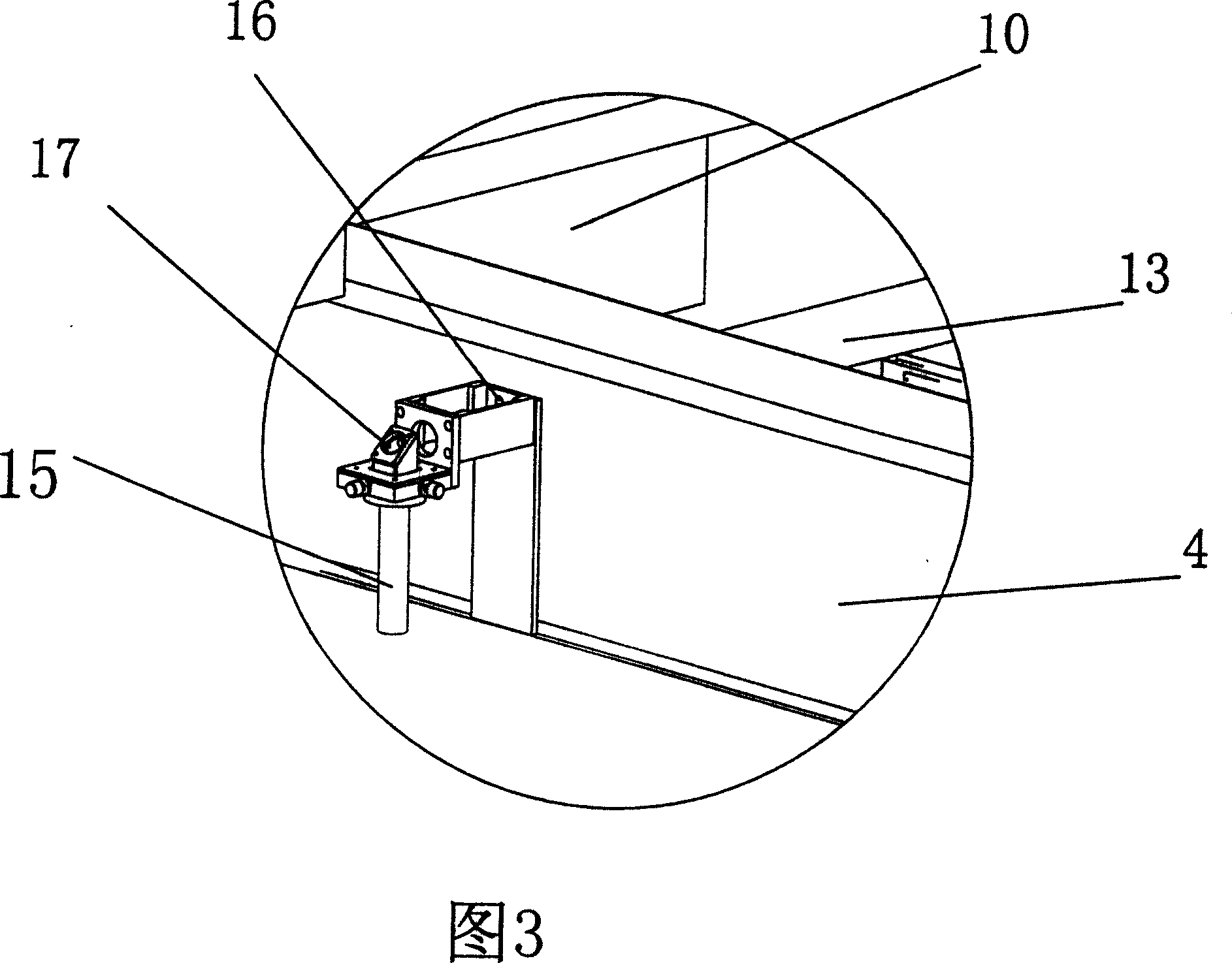
[0024] It is to install the laser tube perpendicular to the beam in the horizontal plane, as shown in Figure 1, the beam 4 is connected to the laser tube cover 10, the laser tube cover 10 is set perpendicular to the beam in the horizontal plane, and the laser tube cover 10 is equipped with a laser tube bracket 11 , the laser tube bracket 11 is connected with the beam 4, the beam 4 is provided with a laser tube hole 12, the laser tube 13 passes through the laser tube hole 12, and the laser tube 13 is fixed on the laser tube bracket 11. As shown in FIGS. 2 and 3 , the laser cutting head support 14 is connected to the front of the beam 4 , and the laser cutting head 15 is connected to the support 14 . The beam 4 is provided with an optical path hole 16 at the front, and the laser cutting head 15 is provided with a mirror 17 for receiving the laser output from the laser tube 13 . It is a multi-head setting, and a laser cutting head 15 is set correspondingly beside each embroidery ...

Embodiment 2

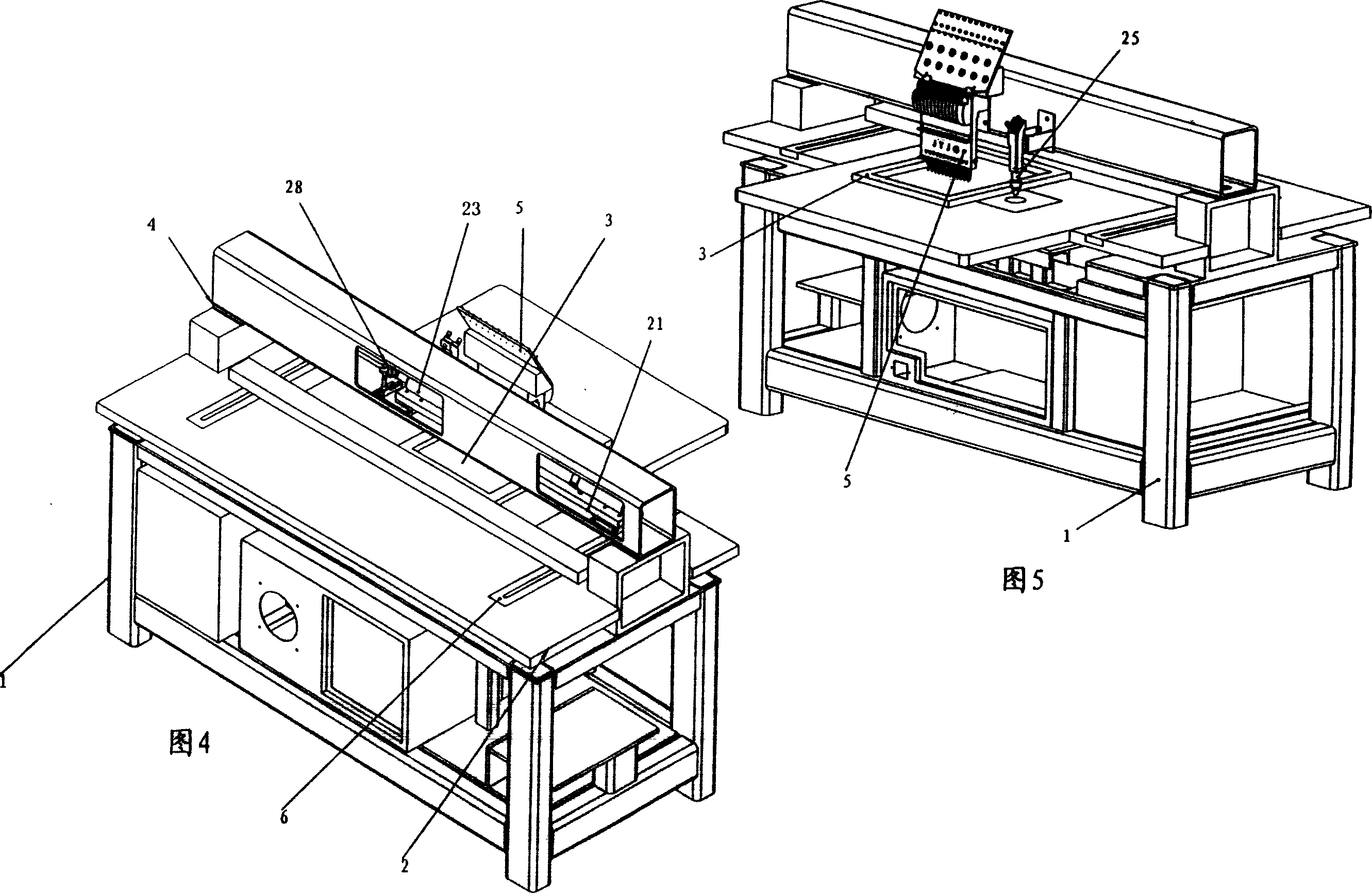
[0026] It is to set the laser tube in the beam. As shown in FIG. 4 , a laser tube bracket 21 is arranged in the beam 4 , the laser tube 23 is fixed on the laser tube bracket 21 , and a reflector 28 is arranged in front of the laser tube 23 (as shown in FIG. 7 ). As shown in Figures 5 and 6, the front of the crossbeam 4 is connected to the laser cutting head support 24, the laser cutting head 25 is connected on the support 24, the crossbeam 4 offers a light hole 26, and the laser cutting head 25 is provided with a laser for receiving the output of the laser tube. Mirror 27. It is a single-head setting, and a laser cutting head 25 is set beside an embroidery device 5 .

Embodiment 3

[0028] It is to set the laser tube parallel to the beam behind the beam. As shown in Figure 8, a laser tube bracket 31 is arranged behind the beam 4, and the laser tube 33 is fixed on the laser tube bracket 31 parallel to the beam 4, and a reflector 38 is provided in front of the laser tube 33 (as shown in Figure 11). Hole 32. As shown in Figures 9 and 10, the front of the crossbeam 4 is connected to the laser cutting head support 34, and the laser cutting head 35 is connected on the support 34. The front of the crossbeam 4 is provided with an optical path through hole 36, and the laser cutting head 35 is provided with a socket for receiving the output of the laser tube. Mirror 37 for the laser. The laser tube bracket can be connected to the laser tube cover, and the laser tube is arranged in the laser tube cover (not shown in the figure). It is also a multi-head setting, and a laser cutting head 35 is set correspondingly beside each embroidery device 5, and the number of la...


PUM


Abstract

The invention discloses an integrative machine with laser embroidery and the manufacturing method. The integrative machine comprises support rack; working plate on the support rack; embroidery frame on the working plate, which can moves in two dimension; connecting beam on the support rack; single embroidery equipment or multiple embroidery equipments on the beam; laser tube, laser path and laser cutting head connected on the beam. The laser cutting head is corresponding to the embroidery equipment and it is set at the side of embroidery equipment. The invention is the subliming machine under the lack of laser cutting machine in embroidery area. It not only continues the superiority of laser machine to the conventional embroidery process but also compensates the lack. It is another jump in efficiency and effect from hand to mechanism and to the laser. The integrative machine with laser embroidery changes the conventional process method of embroidery machine thoroughly.

Description

technical field [0001] The invention belongs to textile processing equipment, in particular to an embroidery equipment, in particular to a laser embroidery integrated machine integrating embroidery and laser cutting and a processing method. Background technique [0002] In the existing computerized embroidery process, two steps are very important, namely the cutting before applique embroidery and the cutting of blanking after embroidery. In the traditional processing technology, the defect of the die cutting method used for cutting before embroidery is that it is easy to produce fabric fringe, and the processing accuracy is limited by the die die, it is difficult to process heterogeneous patterns, the production cycle of the die die is long, the cost is high, and labor The counterpoint effect is not good and wastes time, thus restricting the development of appliqué embroidery. For cutting after embroidery, most of them adopt the hot cutting method, which has the disadvantag...

Claims


Application Information

Patent Timeline
IPC IPC(8): D05C7/00D05C13/00D05B37/00B23K26/00
Inventor 梁伟
Owner WUHAN GOLDEN LASER
Why Eureka
Try Eureka