Micro-structural optical fibre selectively filling method and judge aligning system

A technology of micro-structured fiber and filling method, applied in the direction of cladding fiber, optical waveguide light guide, optical waveguide coupling, etc., can solve the problems of limited application and large gap of discharge parameters, and achieve the effect of reducing filling time and length.

Inactive Publication Date: 2007-08-08
NANKAI UNIV
View PDF0 Cites 12 Cited by
  • Summary
  • Abstract
  • Description
  • Claims
  • Application Information

AI Technical Summary

Problems solved by technology

This method actually has two disadvantages: one is that it can only be used to fill optical fibers with a large difference in the size of the cladding hole and the core hole; the other is that the filling material must be curable or be mixed with a curing agent. This greatly limits the application of this method
However, this method is also subject to certain limitations. It requires that the diameter difference between the central hole and the cladding hole should have a multiple relationship, and its main disadvantage is that for photonic crystal fibers with different structural parameters, the discharge parameters will also vary greatly. For A set of discharge parameters can only be determined through multiple experiments for a fiber with a structural mode, while for an optical fiber with another structural mode, all discharge parameters have to be re-determined

Method used


Image

  • Micro-structural optical fibre selectively filling method and judge aligning system

Examples


Embodiment Construction

[0027] The method for selectively filling microstructured optical fibers and the judging and aligning system of the present invention will be described in detail below in conjunction with the embodiments.

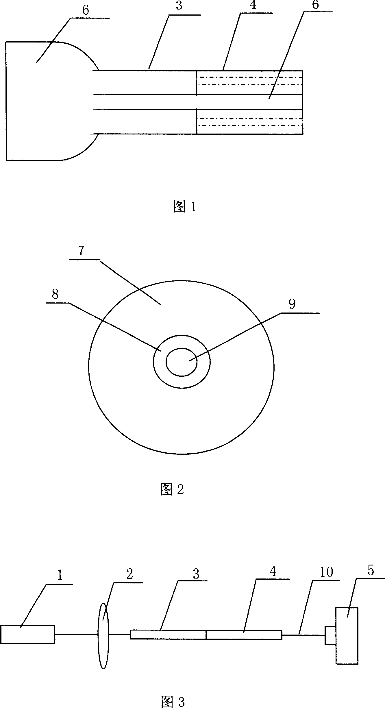
[0028] As shown in Figure 1, the principle of the microstructure optical fiber selective filling method of the present invention is: draw a small section of single-hole optical fiber 3, make its core hole diameter be less than or equal to photonic crystal fiber 4 center hole diameters, combine it with photonic crystal fiber 4 Tight docking, to ensure that the center holes of the two are in a straight line. Then insert one end of the single-hole optical fiber 3 into the liquid to be filled, and use the capillary phenomenon to make the liquid 6 enter the core of the crystal fiber 4 along the core of the single-hole optical fiber 3 .

[0029] The selective filling method of microstructure optical fiber of the present invention is specifically completed by the following steps: ...


PUM


Abstract

It is a microstructure fiber selective filling method and judgment aiming system, the filling system completed by the following steps: 1) pulling to produce single-hole fiber; 2) pre-aligning, processing the produced single-hole fiber and the filling photonic crystal fiber with end-cutting and aiming at the center hole heart; 3) accurate alignment, using the judgment aiming system precisely aiming at the center hole heart of the single hole fiber and photonic crystal fiber; 4) completing filling. The said judgment aiming system comprises laser, coupler, and power meter in serial, and during the measurement, the closely docking single-hole fiber and photonic crystal fiber is placed between the coupler and the power meter. The invention applies to all center hole selective filling of the prohibit-belt fibers that the fiber core hole size is greater than or equal to the single-hole fiber. Requiring only a small section of single-hole fiber, the invention can process a fiber core hole filling of different structures prohibit-belt fibers. Meanwhile, it reduces the length of single-hole fiber and increases the air hole size, and it can appropriately reduce the filling time.

Description

technical field [0001] The invention relates to an optical fiber selective filling method. In particular, it relates to a microstructure optical fiber selective filling method and a judging alignment system that can fill the cores of bandgap optical fibers with various structures. Background technique [0002] At present, the research on photonic crystal fiber is carried out rapidly at home and abroad. The structural feature of the photonic crystal fiber is that there are periodically distributed micro-pore structures extending infinitely along the fiber axis in the cross section. The size and structure distribution of these air holes provides a large design freedom space. At the same time, if new materials are introduced into the air holes, the transmission characteristics of light in them may change, and many photonic crystal fiber functional devices can be obtained. , such as optical attenuators, optical filters, optical switches, dispersion compensators, etc., can also...

Claims


Application Information

Patent Timeline
IPC IPC(8): G02B6/24G02B6/25G02B6/02G02B6/42
Inventor 范万德温福正董孝义
Owner NANKAI UNIV
Why Eureka
Try Eureka