

Laminated cooling walls
A stave, superimposed technology, applied in the direction of cooling devices, etc., can solve the problems of high price, water leakage, good cooling effect of all-copper stave, etc., achieve the effect of reducing copper consumption, good heat conduction effect, and improving use safety
- Summary
- Abstract
- Description
- Claims
- Application Information
AI Technical Summary
Problems solved by technology
Method used
Image

Examples
Embodiment 1
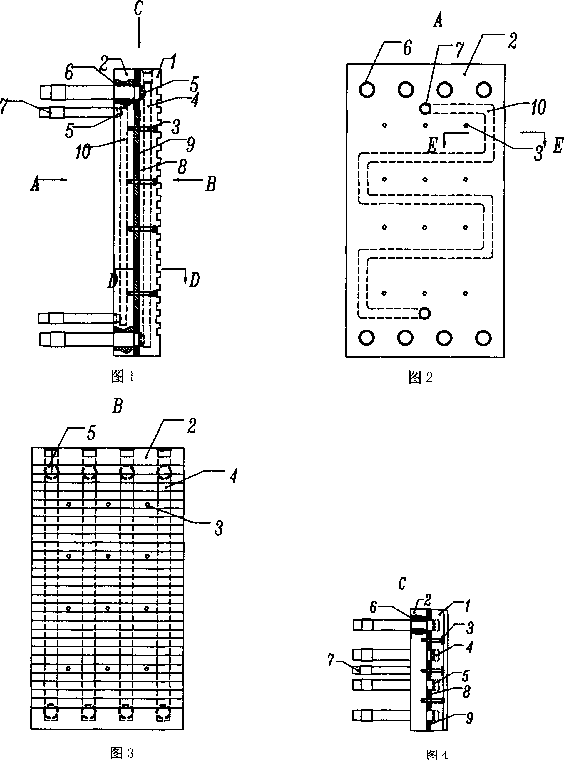
[0035]Embodiment 1: Referring to FIGS. 1 to 6, in Embodiment 1 of the present invention, as shown in FIGS. The length and width of the superimposed surfaces are the same, and the complete superimposition method is adopted, and the connecting bolts 3 are fastened and connected. The laminated wall body 1 is manufactured by drilling copper plates, and the cross-sectional shape V11 of the cooling channel T4 is a compound hole shape or other hole shapes. The base layer wall body 2 is made of cast iron, and has a cooling channel U10 inside, and its cross-sectional shape W12 is a circle or other hole shapes. A gasket 8 is placed between the superimposed layer wall body 1 and the base layer wall body 2. The gasket 8 is a double-layer gasket, and the gap between the double-layer gaskets is filled with a high thermal conductivity filler 9 . The distance from the cooling channel T4 and the cooling channel U10 to the respective wall surfaces is limited to not less than the thickness of t...
Embodiment 2
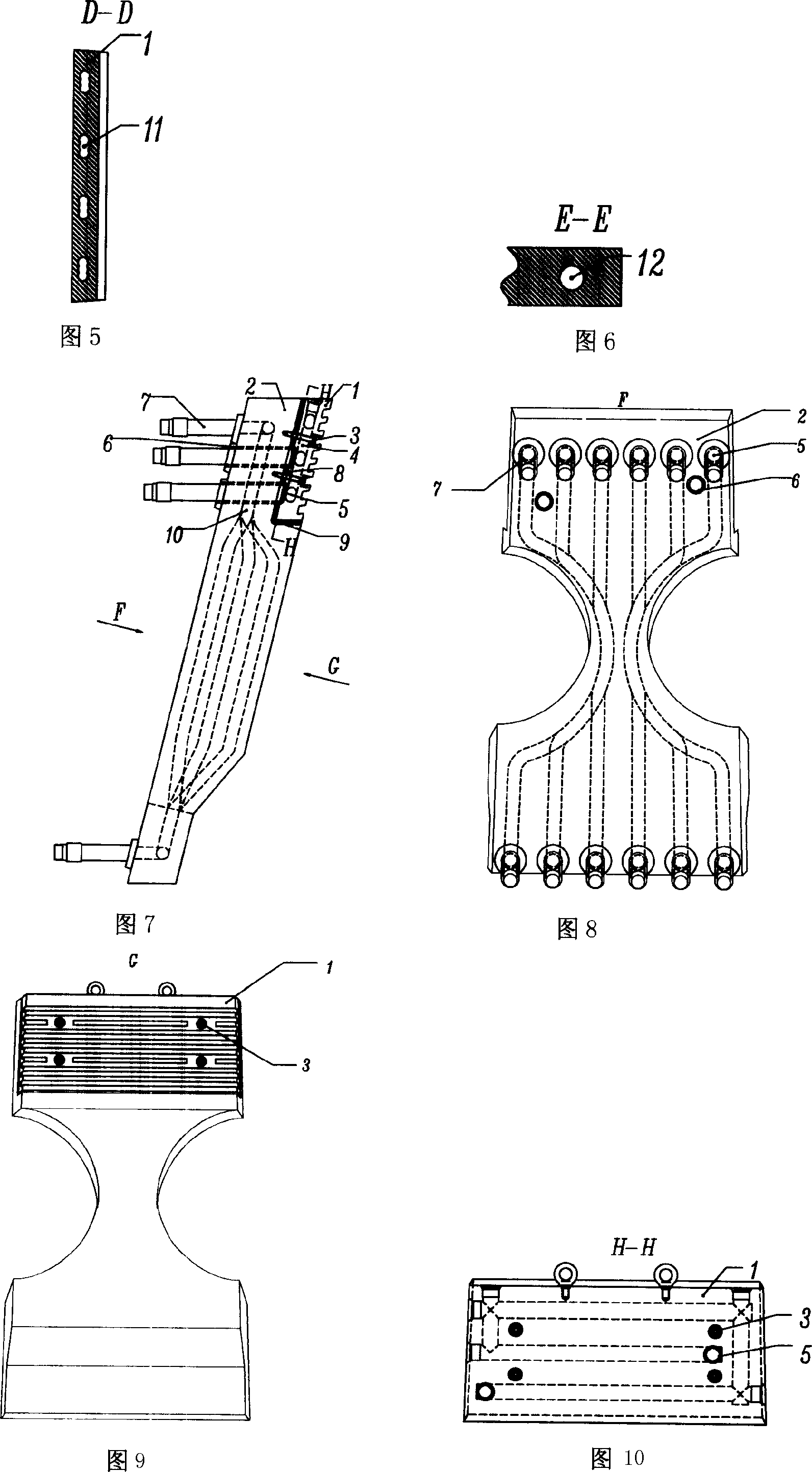
[0041] Embodiment 2: Referring to Fig. 7, Fig. 8, Fig. 9 and Fig. 10, in Embodiment 2 of the present invention, as shown in Fig. 7, the laminated stave comprises a laminated wall body 1 and a base layer The wall body 2 adopts a partial superimposition method, and the superimposed layer wall body 1 and the upper part of the matrix layer wall body 2 are superimposed. Due to the high temperature in the tuyere area of the blast furnace, if a complete cast iron stave is used, the upper part of the stave is located in the tuyere swirl zone It is easy to be damaged, and the lower part can meet the long life requirements of the blast furnace due to the protection of the refractory material layer; now the laminated stave with independent cooling structure and partial superimposition can be used, which can not only improve the safety of the stave in the tuyere area, but also reduce the thickness of the copper stave. Thickness, reduce cost, embodiment 2 can be used in blast furnace tuye...
Embodiment 3
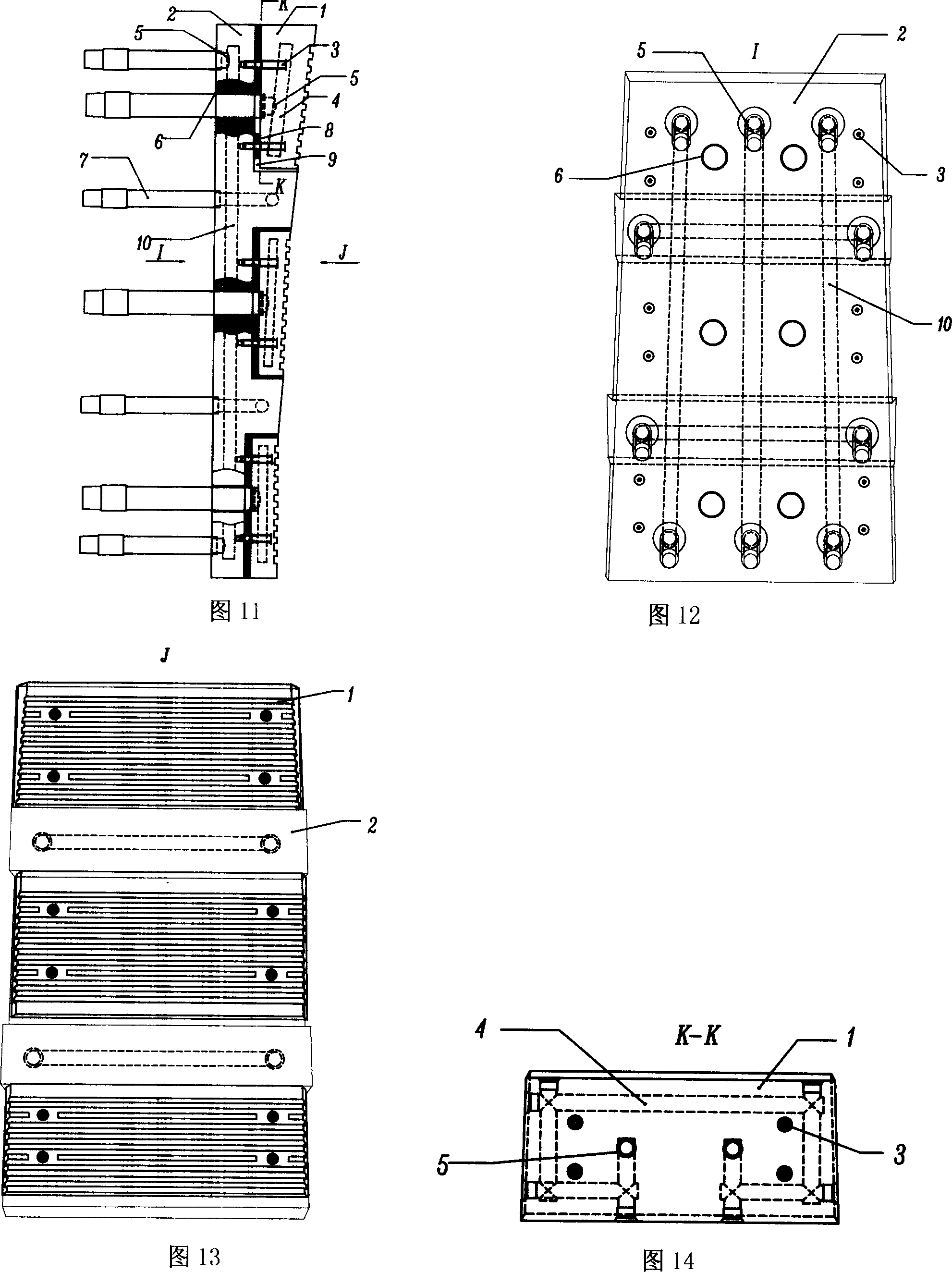
[0042] Embodiment 3: Referring to Fig. 11, Fig. 12, Fig. 13 and Fig. 14, in Embodiment 3 of the present invention, as shown in Fig. 11, the laminated stave comprises a plurality of laminated wall bodies 1 and a matrix The layer wall body 2 adopts a multi-position superposition method and is fastened and connected by connecting bolts 3 . Adopting this embodiment can achieve the technical effect of matching the local cooling intensity of the cooling stave with the heat flow intensity in the blast furnace. According to the change of the heat flow intensity, copper staves with strong cooling capacity are stacked in areas with high heat flow intensity, which not only meets the cooling needs of the blast furnace, The goal of achieving long life of the blast furnace can also reduce the investment cost; Embodiment 3 can be used for staves in the middle of the blast furnace shaft or other high-temperature wall cooling equipment. All the other conditions and effects of embodiment 3 of t...
PUM
 Abstract
Description
Claims
Application Information