Engine with breather apparatus

A ventilation device and engine technology, which is applied to engine components, combustion engines, machines/engines, etc., can solve the problems of difficult configuration space, lack of heating effect, and inability to obtain heating, and achieve generalization and easy installation operations. , the effect of reducing heat

Inactive Publication Date: 2007-08-22
HONDA MOTOR CO LTD
View PDF2 Cites 7 Cited by
  • Summary
  • Abstract
  • Description
  • Claims
  • Application Information

AI Technical Summary

Problems solved by technology

[0006] In the device described in Patent Document 1, when the engine is started, the effect of heating cannot be obtained because the cold air is blown, on the contrary, the freezing of moisture may be promoted because the cold air is blown
In addition, in the device described in Patent Document 2, since the temperature of the vent pipe and the part where the vent pipe is connected to the engine is relatively low, the heating effect cannot be obtained without using a heater with a large heat capacity, and it is assumed that a heater with a large heat capacity is used The heater also has the problem that it is not easy to secure its arrangement space

Method used


Image

  • Engine with breather apparatus
  • Engine with breather apparatus
  • Engine with breather apparatus

Examples


Embodiment Construction

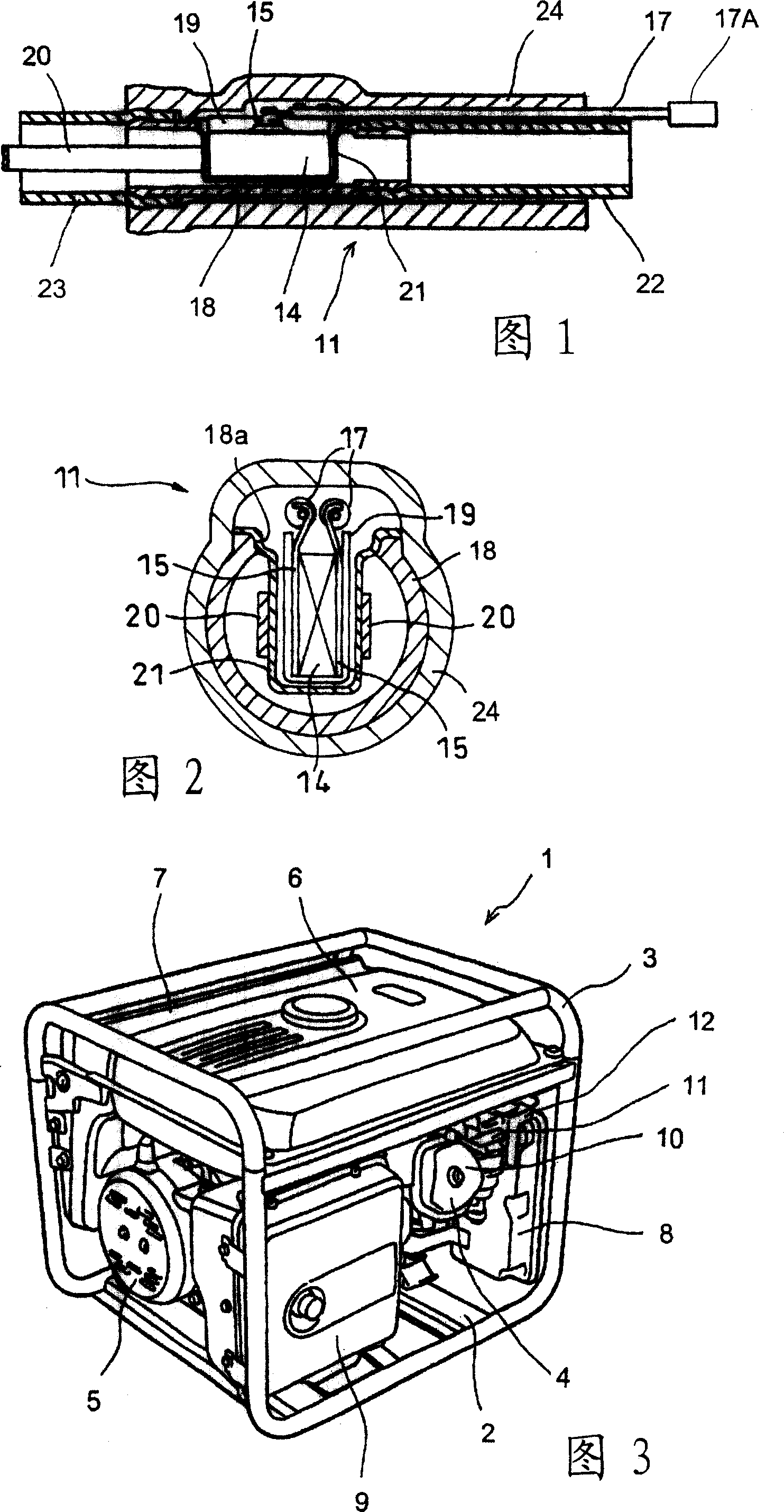
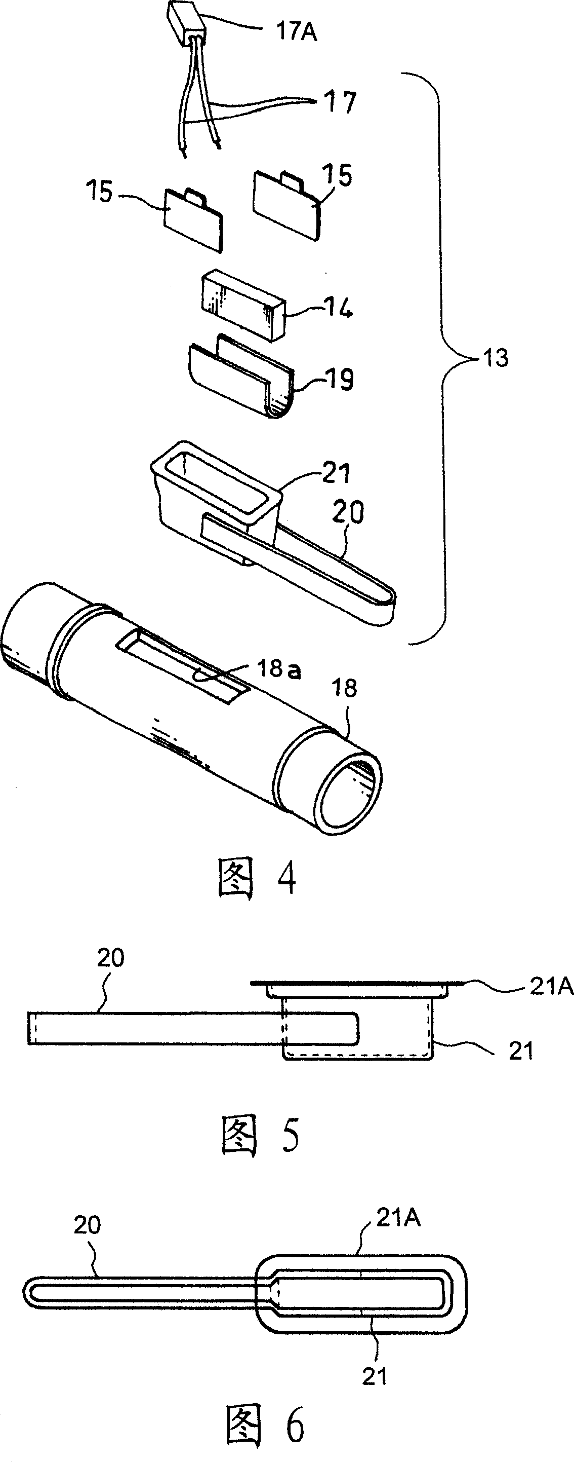
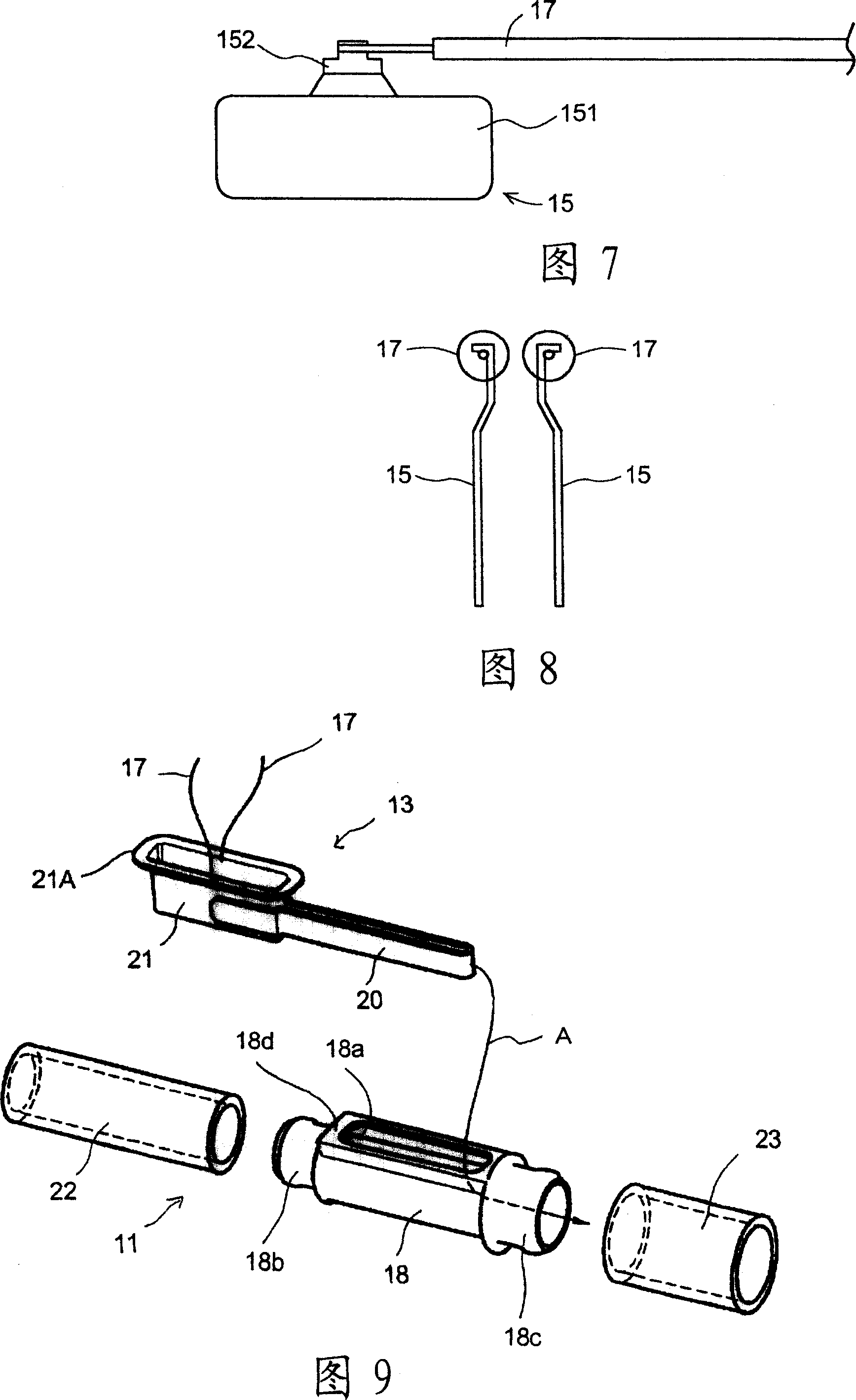
[0042] One embodiment of the present invention will be described in detail below with reference to the drawings. 3 is a perspective view of an engine generator driven by an engine with a breather device according to an embodiment of the present invention. The generator 1 has an engine 4 and a generator main body 5 accommodated at the bottom of a space formed by a bottom plate 2 and a tubular frame 3 . A fuel tank 6 is provided above the engine 4 and the generator main body 5 , and an operation panel 7 is arranged behind the fuel tank 6 . An air cleaner 8 and a muffler 9 are arranged adjacent to the engine 4 . A breather pipe 11 connecting the cylinder head cover 10 of the engine 4 and the air cleaner 8 is provided. The breather pipe 11 passes through a support portion (choke stay) of a chock assembly 12 , and one end of the breather pipe 11 is inserted into a hole formed in the cylinder head cover 10 , and the other end is introduced into the air cleaner 8 inside the housin...


PUM


Abstract

In order to suppress freezing of a water content within a breather tube, a heater ( 13 ) is arranged within a breather tube ( 11 ) joining a cylinder head cover ( 10 ) and an air cleaner ( 8 ). A main body of the breather tube ( 11 ) is constituted by a joint tube ( 18 ) arranged in a middle, and partial tubes ( 22, 23 ) connected to both ends thereof. The heater ( 13 ) has a heating element ( 14 ) corresponding to a heating element, and has a heater case ( 21 ) accommodating the heating element ( 14 ) in a state of being pinched by electrodes ( 15 ), and is arranged in a center portion of the joint 18 . A slot ( 18 a) for inserting the heater ( 13 ) is formed in the joint tube 18 . A heat radiating body ( 20 ) extended along the breather tube ( 11 ) is joined to the heater case ( 21 ). An outer peripheral portion of the breather tube ( 11 ) is covered by an insulative outer tube ( 24 ).

Description

technical field [0001] The invention relates to an engine with a breather, in particular to an engine with a breather which is suitable for suppressing the freezing of moisture in the breather passage. Background technique [0002] In a small general-purpose engine used in an engine generator or the like, the breather pipe is wound outside the engine in order to guide the blow-by gas to the intake passage. Therefore, in such an engine, the vent pipe is exposed to the atmospheric temperature, so that in a cold region where the atmospheric temperature is extremely low, the moisture contained in the blow-by air passing through the vent pipe may freeze to block the vent pipe. [0003] As a countermeasure against this problem, for example, in the engine described in Japanese Patent Application Laid-Open No. 8-151917, an attempt has been made by guiding the cooling exhaust gas of the high-temperature part during engine operation, that is, the cylinder and the muffler, etc. to the ...

Claims


Application Information

Patent Timeline
Patent Type & Authority Applications(China)
IPC IPC(8): F01M13/00
CPCY02T10/166Y02T10/146
Inventor 出口尚广浅井孝一中村利和齐藤嶺中川胜博藤田泰
Owner HONDA MOTOR CO LTD
Why Eureka
Try Eureka