
Aligning system and aligning method based on image technique

An alignment system and image technology technology, applied in the alignment field of packaging lithography machines, can solve the problems of complex design and assembly, high manufacturing cost, and achieve the effects of simple design, improved productivity and reduced cost

Active Publication Date: 2007-08-22
SHANGHAI MICRO ELECTRONICS EQUIP (GRP) CO LTD
View PDF1 Cites 19 Cited by
  • Summary
  • Abstract
  • Description
  • Claims
  • Application Information

AI Technical Summary

Problems solved by technology

[0004] In the Chinese patent application number 200610023153, the exposure device in the equipment is designed as a wide-band mode, mainly to eliminate the chromatic aberration problem of the optical projection system in the alignment band, but the manufacturing cost of this exposure device is relatively high, and the design and assembly are complicated

Method used


Image

  • Aligning system and aligning method based on image technique
  • Aligning system and aligning method based on image technique
  • Aligning system and aligning method based on image technique

Examples


Embodiment Construction

[0027] The alignment system and alignment method based on image technology of the present invention will be further described in detail below.

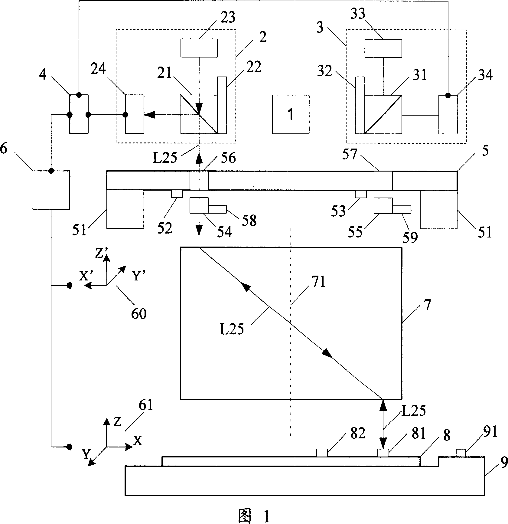
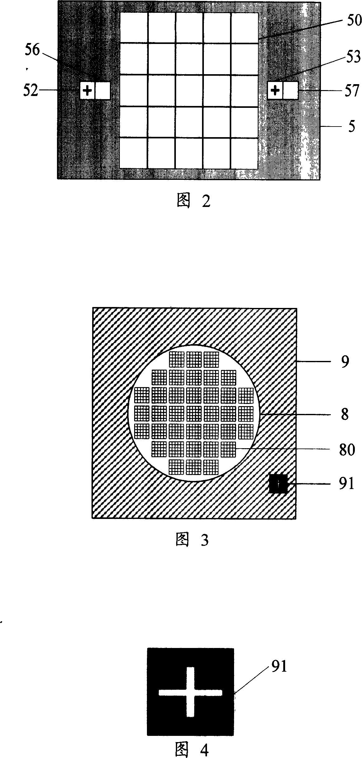
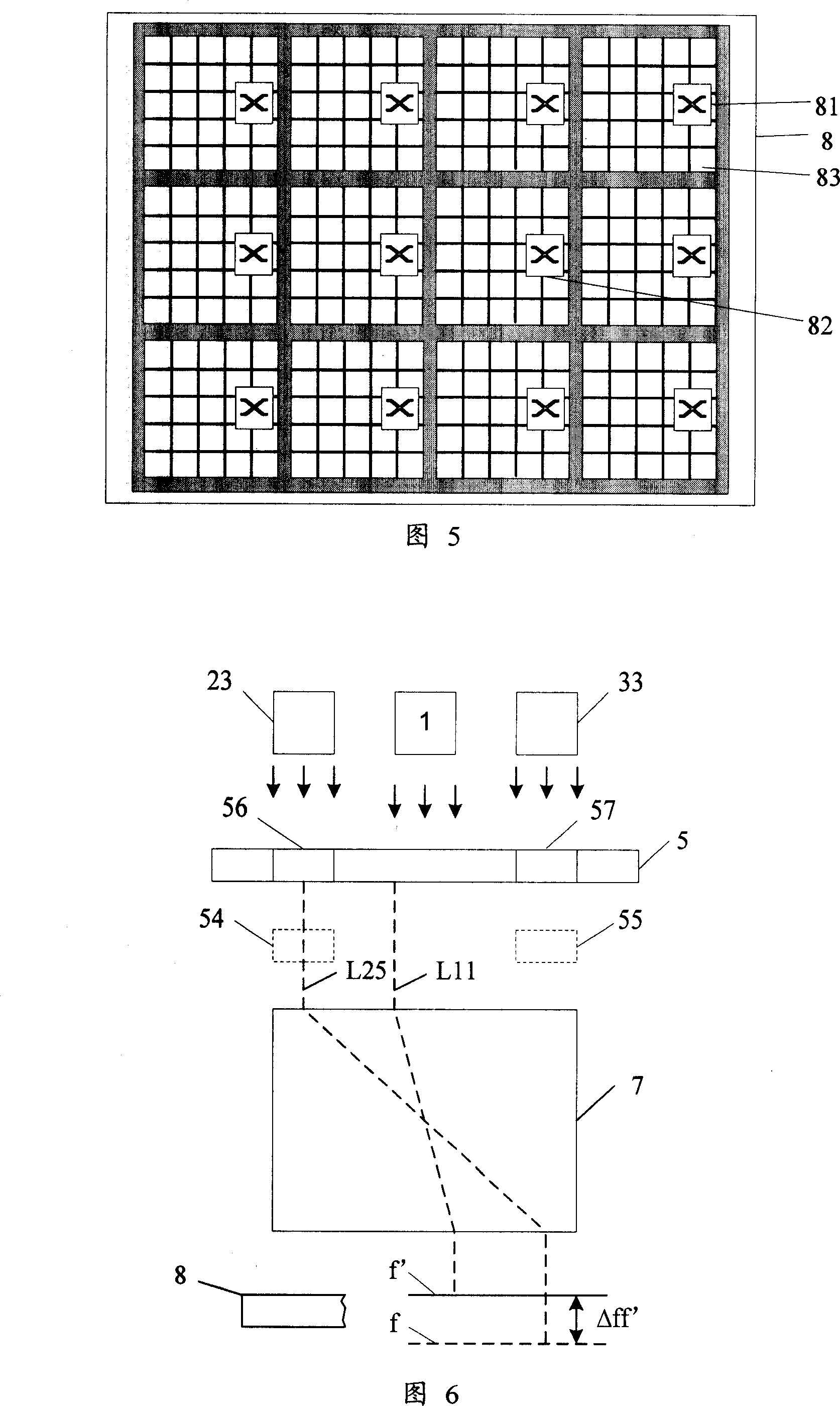
[0028] As shown in FIG. 1 , the projection exposure apparatus for manufacturing integrated circuits or printed circuit boards at least includes a reticle 5 depicting an exposure circuit pattern, which is placed on a stage 51 and is controlled by a stage motion control device 60 Move in X', Y', Z' directions; apply photoresist to the exposure object 8, which is placed on the film stage 9, and moves in the X, Y, Z directions through the film stage motion control device 61; optical The projection system 7 can project and transfer the circuit pattern on the reticle 5 to the exposure object 8 through the ultraviolet exposure of the exposure light source 1, and the magnification of the optical projection system 7 determines the projection of the circuit pattern on the reticle 5 to the exposure object 8 The size of the upper back circuit pat...


PUM


Abstract

The invention provides an aligning system and method based on image technique. And the system is arranged in a projection exposure device composed at least of light source, mask, mask bearing table, mask bearing table motion controller, optical projection system, exposed object, plate bearing table and plate bearing table motion controller, and comprises at least two position aligners uniformly distributed by using the optical axis of the optical projection system as axis, mask label arranged on the mask, exposed object label arranged on the exposed object, and reference label arranged on the plate bearing table, where the position aligners detect and transmit position information of various labels to the motion controllers to control position adjustment of the mask, exposed object and plate bearing table to align them, and the aligning system is equipped with an aberration compensation lens and a lens calibrating unit corresponding to each position aligner. And the invention can reduce system manufacturing cost and system complexity by adopting narrow waveband design mode and cooperating with the aberration compensation lens.

Description

technical field [0001] The invention relates to the alignment of a packaging photolithography machine, in particular to an alignment system and alignment method based on image technology. Background technique [0002] In lithography packaging equipment, the pins or circuit patterns drawn on the reticle should be imaged on the surface of the exposure object coated with photoresist and other photosensitive materials through the projection exposure device. The silicon wafer where the circuit pattern will be packaged. Afterwards, pins or circuit patterns are formed on the exposed object through a subsequent etching process. [0003] Before using the projection exposure device for exposure, the position of the mask and the exposure object must be aligned. Usually, there are marks for alignment on the side of the mask and the exposure object. Through a certain position alignment device and position alignment method, A relative positional relationship between the mask and the exp...

Claims


Application Information

Patent Timeline
Patent Type & Authority Applications(China)
IPC IPC(8): G03F9/00G03F7/20H01L21/027
Inventor 王鹏程徐兵
Owner SHANGHAI MICRO ELECTRONICS EQUIP (GRP) CO LTD
Learn More