
System, method and apparatus for testing long-distance frame time delay

A test frame and remote frame technology, applied in the field of communication, can solve the problems of time-consuming and labor-intensive communication protocols, the inability to solve the problem of common clock reference, and cumbersome calibration, etc., to achieve the effect of ensuring long-term stability

Inactive Publication Date: 2007-08-22
HUAWEI TECH CO LTD
View PDF0 Cites 25 Cited by
  • Summary
  • Abstract
  • Description
  • Claims
  • Application Information

AI Technical Summary

Problems solved by technology

The defect of this technical solution is: the use of commercial rubidium frequency standard and GPS frequency standard is expensive, which increases the test cost; and even if commercial devices such as rubidium frequency standard and GPS frequency standard are used, it still cannot solve The common clock reference problem when testing remote communication networks or communication equipment; in addition, this technical solution does not provide an integrated solution for testing and measurement, and the time delay of testing services requires network installation and calibration, which is cumbersome and time-consuming laborious
Although this technical solution relies on the Ethernet network to implement the clock synchronization protocol, the test frame carrying the time stamp cannot cross the three-layer switching network, so it cannot realize the long-distance delay test. The Qos test will be meaningless; in addition, IEEE.1588 technology is not yet mature in application at present, and realizing this technology requires a dedicated Ethernet PHY layer chip, and the Ethernet PHY layer chip supports the addition of synchronization information (Sync information) timestamps and extraction; but there is no mature application of IEEE.1588 commercial chip at present, and the clock synchronization protocol used when adopting this technical solution is relatively complicated, which brings considerable difficulties to the realization of this technical solution
[0006] From the above content, it can be seen that the existing technology is difficult to meet the requirements for testing the service delay of cross-regional and large-scale communication networks, even if the service delay is tested for communication networks or communication equipment in a small area, There are also problems such as high test cost, the need for network installation and calibration for each test task, which is cumbersome, time-consuming and labor-intensive, and complex communication protocols are difficult to implement.

Method used


Image

  • System, method and apparatus for testing long-distance frame time delay
  • System, method and apparatus for testing long-distance frame time delay

Examples


Embodiment Construction

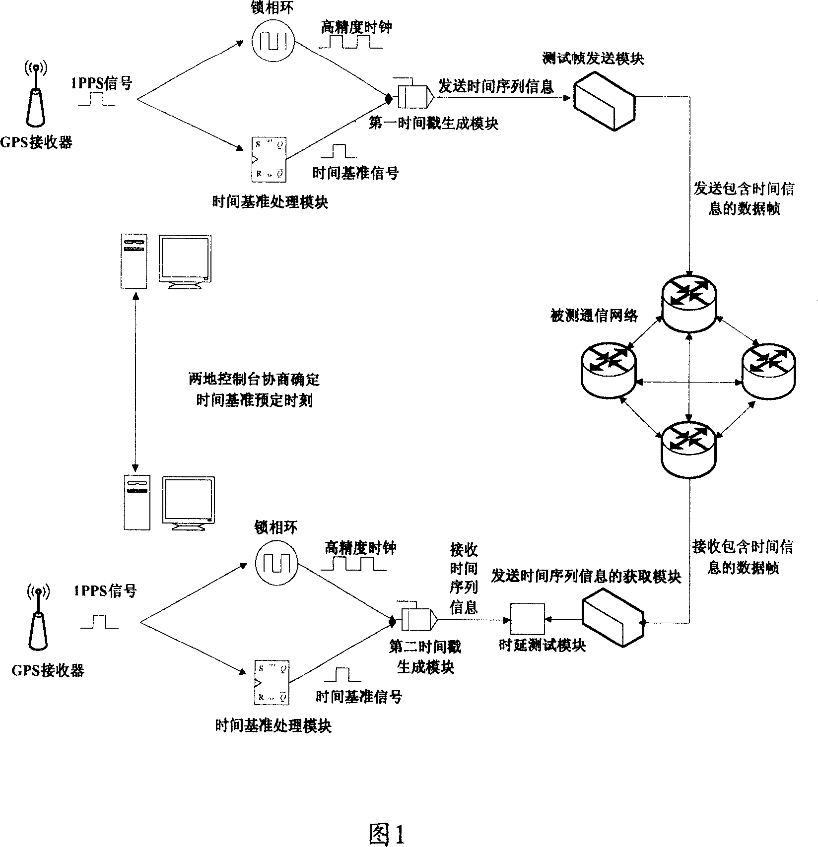
[0025] In order to facilitate the understanding of the technical solutions provided by the embodiments of the present invention, firstly, we will introduce the requirements of communication equipment manufacturers and communication service operators when testing large-scale, cross-geographic communication network service time delays. This is because communication equipment manufacturers 1. Communication service operators need to accurately measure the technical index of service delay to provide guidance for equipment selection and optimization of network layout and wiring. transmission delay on the .

[0026] Generally speaking, the following requirements are usually required for the test of service delay in a wide range of geographical areas:

[0027] First, the test has high requirements for the accuracy of the clock system: a large number of tests for the core network and full clock synchronization network require the clock accuracy of the test instrument to be at least 1 t...


PUM


Abstract

A method for testing time delay of remote frame can provide high accurate clock system to ensure high accurate clock and common time basis required by service time delay test of trans-regional communication network and to ensure long period of stability for clock system on each individual test instrument as well as to ensure clock accuracy required by user and used between multi-set test instrument when test of service time delay on tested communication network or tested communication device is carried out.

Description

technical field [0001] The invention relates to the communication field, in particular to a system, method and device for testing remote frame delay. Background technique [0002] With the wide application of communication equipment and communication services, in the field of communication equipment manufacturing and communication service operation, the precise measurement and evaluation of QoS (Quality of Service) and performance indicators (such as throughput) of communication equipment and communication networks have also become It is becoming more and more important, and the service delay (Service Delay) index is particularly critical for the rapidly growing voice and video services based on IP bearer. [0003] In the prior art, there are usually two technical solutions to test the service delay of the communication network: [0004] The first technical solution is to use the external reference clock access interface provided by the existing test instrument to access th...

Claims


Application Information

Patent Timeline
IPC IPC(8): H04L12/26H04B17/00H04M3/22H04Q7/34H04B17/309
Inventor 杨洋
Owner HUAWEI TECH CO LTD
Learn More