Numerical-control machine tool magnetic suspension linear feeding system

A linear feed system, CNC machine tool technology, applied in the direction of the propulsion system, control/regulation system, electromechanical devices, etc., can solve the problems of poor stiffness performance, poor bearing capacity, instability, etc., to achieve improved bearing capacity and good stiffness performance , the effect of improving efficiency

Inactive Publication Date: 2007-08-29
DALIAN JIAOTONG UNIVERSITY
View PDF2 Cites 62 Cited by
  • Summary
  • Abstract
  • Description
  • Claims
  • Application Information

AI Technical Summary

Problems solved by technology

[0007] The Changchun Institute of Optics, Fine Mechanics and Physics of the Chinese Academy of Sciences discloses an ultra-precision micro-displacement guide rail magnetic levitation method and its device in the patent document CN1214892C, but this patent only uses two electromagnets to generate the levitation force, so the mobile platform rotates along the horizontal The degree of freedom is not limited, so it becomes unstable; in this patent, the two electromagnets used to generate the levitation force also play a guiding role, and decoupling control must be performed, which increases the complexity of the control system; the patent used The linear motor has a unilateral stator structure, and there is a unilateral magnetic pull between the linear motor stator and the mover, which causes a great burden on the mobile platform
[0008] Shanghai University discloses an industrial application type active magnetic levitation guide rail linear motor feed platform in patent document CN1244432C, but the fixed part in this patent is a simply supported beam structure supported at both ends, with poor rigidity, easy deformation, and low load-carrying capacity. Poor; the linear motor in this patent has a bilateral mover structure, and both sides of the mover are fixed on the moving parts, which increases the useless weight of the moving parts

Method used


Image

  • Numerical-control machine tool magnetic suspension linear feeding system
  • Numerical-control machine tool magnetic suspension linear feeding system
  • Numerical-control machine tool magnetic suspension linear feeding system

Examples


Embodiment Construction

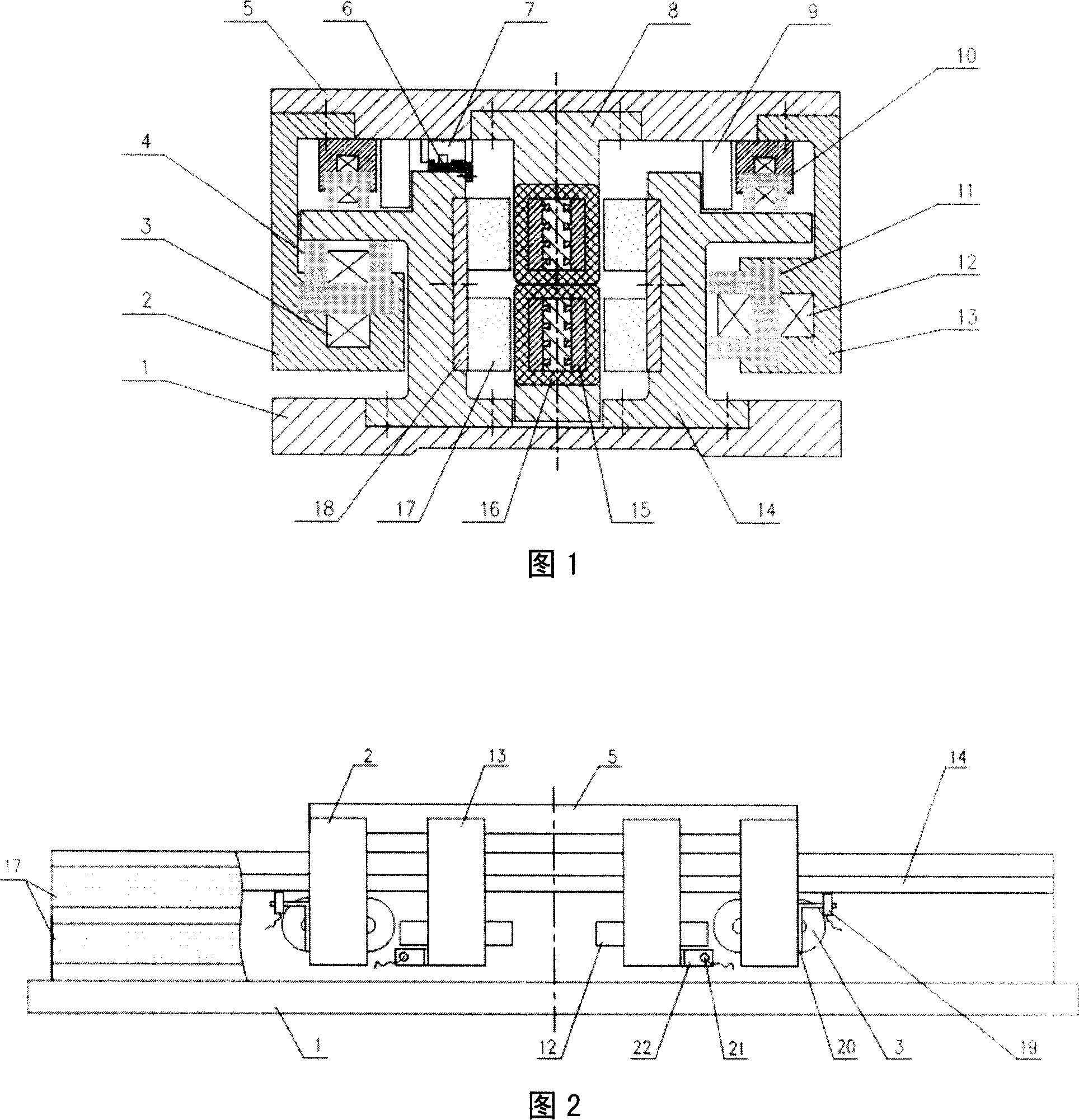
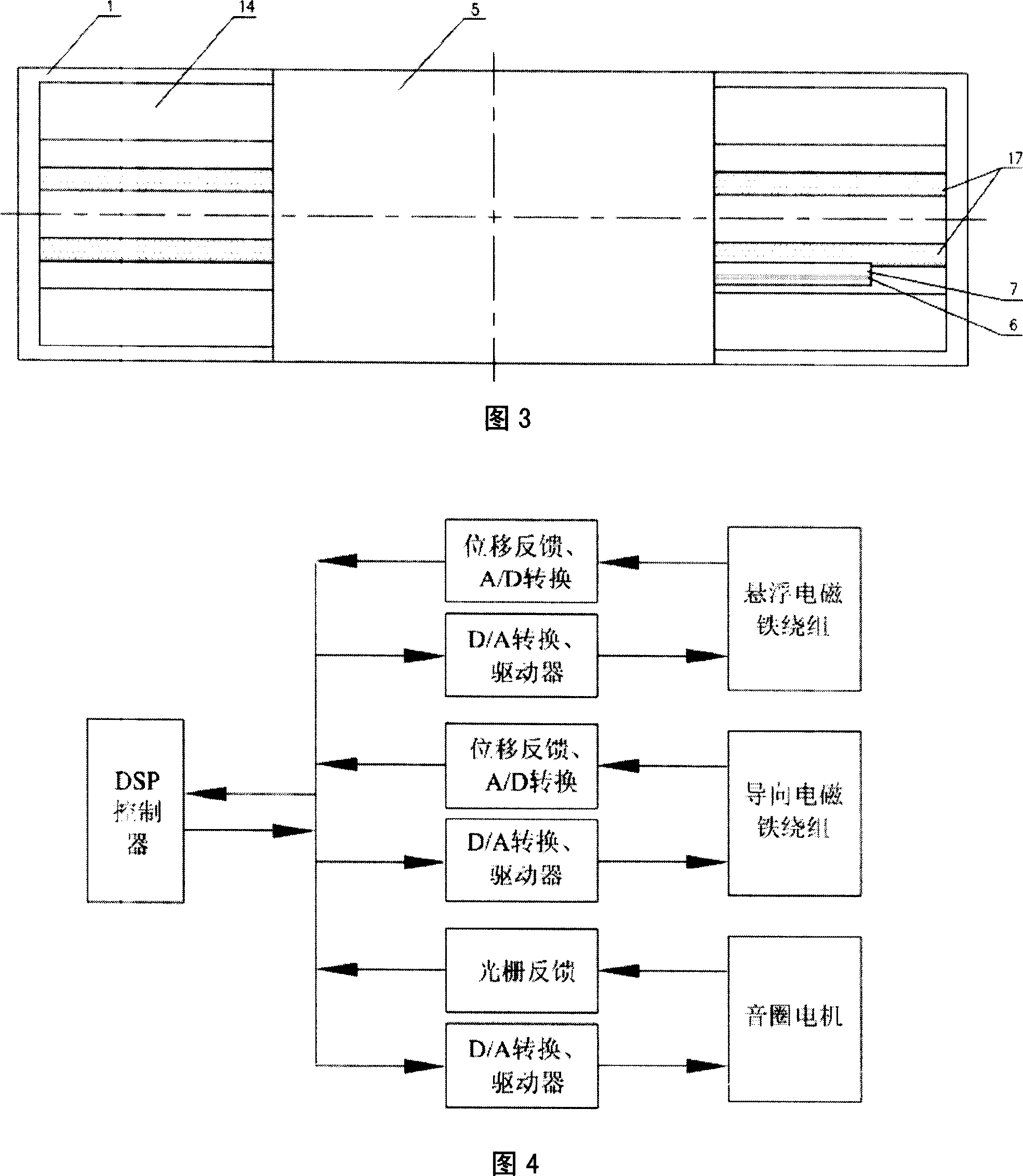
[0026] First, referring to accompanying drawings 1, 2, and 3, the maglev linear feed system for a numerically controlled machine tool of the present invention includes a base 1, two guide rails 14 fixed on the base 1, linear motor stator components 17, 18, installed in the working Four sets of differential levitation electromagnets 4 and 10 below the four corners of platform 5, two sets of guide electromagnets 11 installed next to the levitation electromagnet 10, and two sets of guide electromagnets 11 installed next to the levitation electromagnets 4, 10 and guide electromagnet 11 Eddy current displacement sensors 19, 21, linear motor mover components 8, 15, 16 installed under the workbench 5, grating scale 6 installed on the guide rail, grating reading head 7 installed under the workbench, installed under the workbench The supporting device 9 and the guide rail protective cover (not shown in the figure).

[0027]A working cycle of the present invention will be described in d...


PUM


Abstract

The invention relates to new type numerically controlled machine tool magnetic suspension feeding system. It includes engine base, two guide rails, linear motor stator part, four pairs of differential action suspension electromagnets, two pairs guide electromagnets, linear motor mover part, optical grating measuring system, and support device. The control system of the invention adopts clearance control system between DSP main controller suspension electromagnet, guide electromagnet, and the guide rail, and linear motor servo control system. Thus the invention can eliminate platen no touch support and guide, remove frictional wear, increase feed speed and positioning accuracy, supply enough bearing capacity and thrust, can be used in practical processing.

Description

technical field [0001] The invention relates to a feeding system of a numerically controlled machine tool, which is supported and guided by a magnetic force and driven by a linear motor, and can realize high-speed, high-acceleration, and high-precision frictionless feeding of a machine tool workbench. Background technique [0002] The traditional machine tool feed system contains many intermediate transmission links, the inertial mass of the whole system is large, and the dynamic performance of the system is poor. Moreover, the elastic deformation, friction and wear, and backlash of the intermediate link during the movement will cause hysteresis and nonlinear errors in the positioning and feeding movement, which will affect the machining accuracy. In addition, the inherent defects of the screw drive make it difficult for the table to achieve high feed speed and accuracy. [0003] In order to improve the feed speed, acceleration and positioning accuracy of the machine tool w...

Claims


Application Information

Patent Timeline
Patent Type & Authority Applications(China)
IPC IPC(8): B23Q5/34B23Q1/30B23Q1/34H02K41/02H02N15/00G05D3/20G05D27/02
Inventor 葛研军张文跃蒋成勇籍延坤王磊陈铁年韩勇
Owner DALIAN JIAOTONG UNIVERSITY
Why Eureka
Try Eureka