Dual-roving yarn guide for drafting device of weaving machine

A drafting device and yarn guide technology, applied in spinning machines, drafting equipment, textiles and papermaking, etc.

Inactive Publication Date: 2007-08-29
MASCHINENFABRIK RIETER AG
View PDF2 Cites 7 Cited by
  • Summary
  • Abstract
  • Description
  • Claims
  • Application Information

AI Technical Summary

Problems solved by technology

Fixing the roving guide by screwing it to the roving guide rail has the disadvantage that the roving guide rail must be equipped with a large number of internal threads
Furthermore, it is only possible, if at all possible, only to a great extent that the roving guide is moved along the roving guide rail to adjust its position with respect to the drafting device

Method used


Image

  • Dual-roving yarn guide for drafting device of weaving machine
  • Dual-roving yarn guide for drafting device of weaving machine

Examples


Embodiment Construction

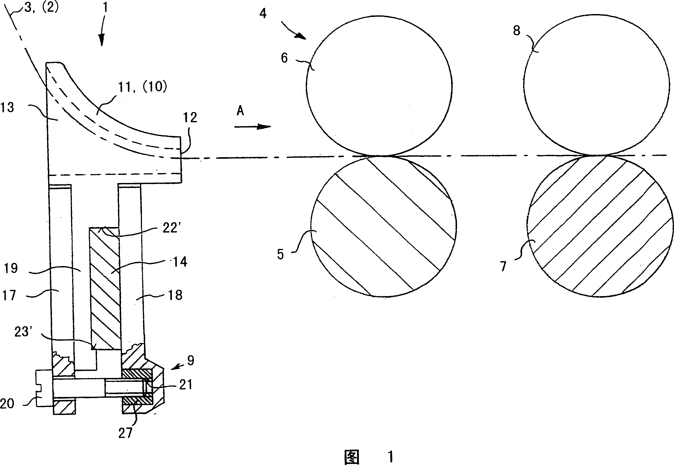
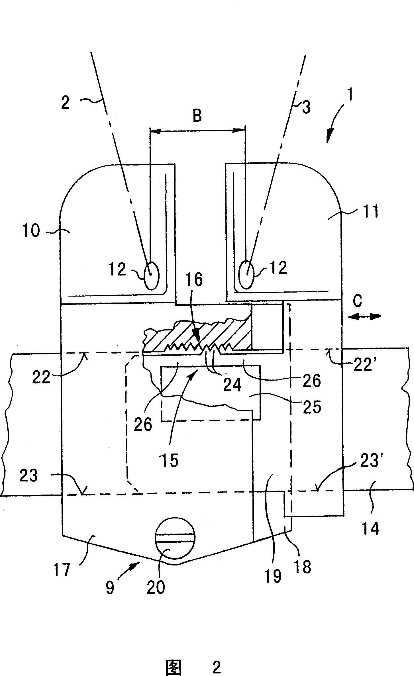
[0018] The double roving guide shown in FIGS. 1 and 2 feeds two fiber strands or rovings 2 and 3 into the drafting device 4 . The drafting device 4 consists of a number of roller pairs, of which only two roller pairs 5 , 6 and 7 , 8 are shown in FIG. 1 . Bottom rollers 5 and 7 are driven and they are under pressure from top rollers 6 and 8 respectively. In the case of the drafting device 4 of the ring spinning frame, the bottom rollers 5, 7 are designed as grooved rollers running through in the longitudinal direction of the machine. The rovings 2, 3 are fed into the drafting device 4 in the transport direction A and drawn to the desired fineness. It is provided in a manner not shown that a compression device can also be provided directly downstream of the drafting device 4 following the pair of delivery rollers, in which compression device the two rovings 2 and 3 are compressed and compacted in separate compression zones. Then the drawn fiber strands are either fed into a co...


PUM


Abstract

In a double roving guide for the stretching tool of a textile machine, having two separated guiding funnels for spaced guiding of two fibrous rovings to a roller pair and clamping device for fixing the roving guide to a roving guide rail, the space between the guiding funnels is variable and a lockable adjusting device is provided in the variable space.

Description

technical field [0001] The invention relates to a double roving guide for a drafting device of a textile machine, wherein the double roving guide has two separate guide horns for feeding two rovings at a distance to the drafting device, and There is a clamping device to fix the double roving guide on the roving guide rail. [0002] Furthermore, the invention relates to a guide horn constituting a single part for such a double roving guide. Background technique [0003] This double roving guide is placed directly at the drafting unit entry, allowing two fiber slivers or rovings to be fed to the drafting unit. In this case, the two rovings are not joined, but are fed into the drafting device at a small distance and are drawn separately in the drafting device. This double roving guide is especially suitable for use in drafting devices on ring spinning machines. It can be provided here that the two drawn-out fiber strands are brought together next to the pair of delivery roll...

Claims


Application Information

Patent Timeline
Patent Type & Authority Applications(China)
IPC IPC(8): D01H13/04D01H5/70
CPCD01H13/04D01H5/70
Inventor W·莱纳V·沙弗
Owner MASCHINENFABRIK RIETER AG
Why Eureka
Try Eureka