
Multi-level power converter of light unit cascade

A power converter and unit-level technology, applied in the direction of converting AC power input to DC power output, converting AC power input to AC power output, and output power conversion devices, can solve the problem of increasing the complexity of input transformer design and relying on large Capacity electrolytic capacitors, reducing the capacity of DC capacitors and other issues, to achieve the effect of simplifying the control system and power device drive power structure, reducing the capacity of reactive components, and improving reliability

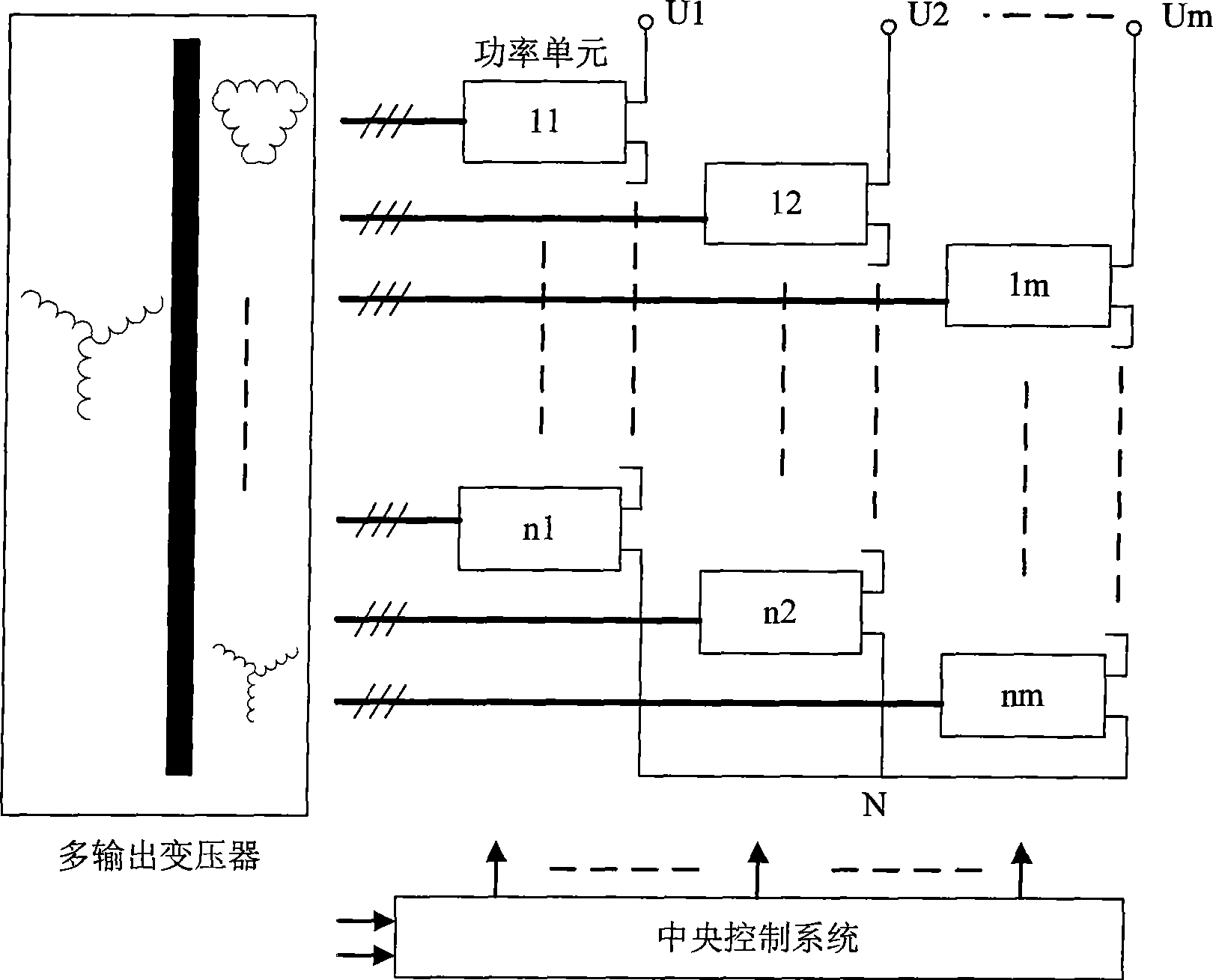
Inactive Publication Date: 2011-04-13
INST OF ELECTRICAL ENG CHINESE ACAD OF SCI
View PDF1 Cites 2 Cited by
  • Summary
  • Abstract
  • Description
  • Claims
  • Application Information

AI Technical Summary

Problems solved by technology

[0009] Each power unit generates a large number of harmonics due to the use of large-capacity capacitors, so it is necessary to design an input transformer with multiple output windings, and keep each winding at a certain angle to reduce harmonics, which increases the complexity of the input transformer design;
[0010] The control system of each power unit and the drive power supply circuit of the power device are complicated. When the main circuit is powered on, the control system of each unit is in a power-off state, which will reduce the reliability of the entire device.
[0011] In Chinese patent 01115364.4, each output phase is formed by cascading a matrix conversion unit and an H-bridge inverter unit, which significantly reduces the DC capacitor capacity, but the H-bridge inverter unit still relies on large-capacity electrolytic capacitors to obtain DC power.

Method used


Image

  • Multi-level power converter of light unit cascade
  • Multi-level power converter of light unit cascade
  • Multi-level power converter of light unit cascade

Examples


Embodiment Construction

[0041] The present invention will be further described below in conjunction with the accompanying drawings and specific embodiments.

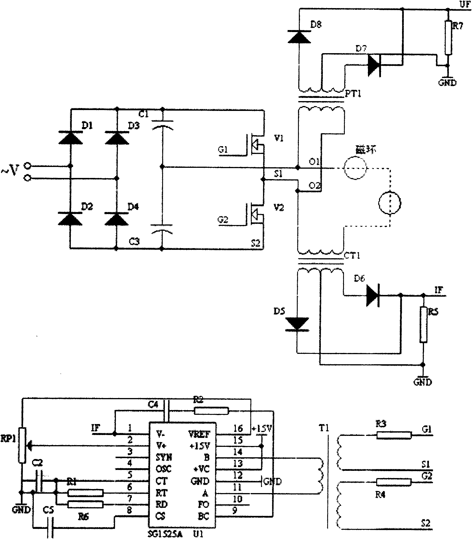
[0042] image 3 It is the light unit cascaded power converter of the present invention. Consists of a multi-output transformer, light unit, central control system and pump power supply. Such as image 3 As shown in , it is assumed that the power converter outputs m phases, and each phase is formed by cascading n light-duty units, that is, there are nxm light-duty units in total. The primary side of the multi-output transformer is connected to the high-voltage power supply by terminals A, B, and C, and the secondary windings form a group of three phases, marked as a, b, and c. Since the number of light-duty units is nxm, the number of secondary winding groups is also nxm. If the numbers of the light-duty units and the corresponding secondary windings of the transformer are 11, 12, ..., nm, the three-phase secondary windings pass through 11abc...


PUM


Abstract

A light unit cascade multi-level power converter comprises: an outputting transformer, a light unit, a central control system and a pump electrical source. The light unit comprises an unit power circuit, an unit electric source and an unit control system. The unit power circuit is connected to a group of sub-winding group of the multi-output transformer by three ends to output by two ends y1 and y2, and is connected to other light unit phase with the same phase. The unit power circuit has five structures, each structure has a plurality of structure style due to using different power devices. An electrical waveform at the light unit outputting side closes to sine. A pump power supply provides power for the central control system, the unit control system of the light unit and a driving power of the power device. The pump power supply outputs a high-frequency square wave alternating current which crosses each light unit and the control system through a high-voltage insulation cable, each light unit and the control system obtain a multi-way isolated low voltage direct current power supply by coupling magnetic loops insulative each other.

Description

technical field [0001] The invention relates to a switch type power conversion device, in particular to a light unit cascaded multilevel power converter. Background technique [0002] A power converter is a device for converting electrical power, characterized by the conversion of the amplitude, frequency, and phase of voltage or current. Devices with this function include transformers, rotary converters, power amplifiers and switching power converters. The unit cascaded multilevel power converter belongs to a kind of switching power converter. [0003] The topology of the unit cascaded multilevel power converter is as follows: figure 1 As shown, it consists of multi-output transformer, power unit and central control system. [0004] Such as figure 1 As shown, the primary side of the multi-output transformer is connected to the power grid, and the number of secondary windings (3-phase as a group) is equal to the number of power units. If m phases are output, and each ph...

Claims


Application Information

Patent Timeline
Patent Type & Authority Patents(China)
IPC IPC(8): H02M5/00H02M5/12H02M5/44H02M5/458H02M7/48H02M7/5387H02M1/12H02M1/42
CPCY02B70/126Y02B70/10
Inventor 杜海江李耀华
Owner INST OF ELECTRICAL ENG CHINESE ACAD OF SCI
Learn More