Increasing measurement rate in time of flight measurement apparatuses

A time-of-flight and measuring equipment technology, applied in photogrammetry/video metrology, measuring instruments, measuring devices, etc., can solve problems such as light pulse rate limitation

Active Publication Date: 2007-09-12
LEICA GEOSYSTEMS AG
View PDF1 Cites 50 Cited by
  • Summary
  • Abstract
  • Description
  • Claims
  • Application Information

AI Technical Summary

Problems solved by technology

However, these conventional embodiments suffer from limitatio...

Method used


Image

  • Increasing measurement rate in time of flight measurement apparatuses
  • Increasing measurement rate in time of flight measurement apparatuses
  • Increasing measurement rate in time of flight measurement apparatuses

Examples


Embodiment Construction

[0016] The principles of the embodiments described herein describe the structure and operation of several examples that illustrate the invention. It is to be understood that the drawings are diagrammatic and schematic representations of such exemplary embodiments, and therefore do not limit the scope of the invention, nor are they necessarily drawn to scale. Well-known devices and procedures are excluded to avoid overwhelming the discussion with details well known to those skilled in the art.

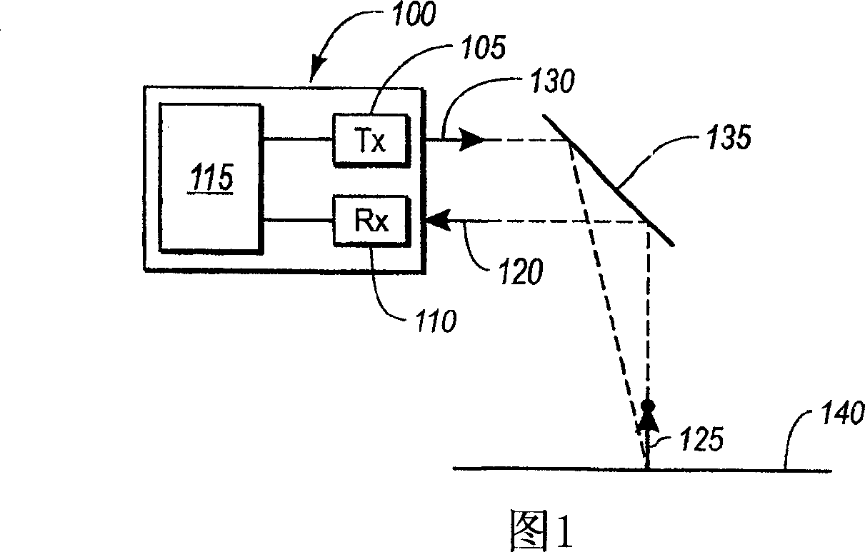
[0017] Referring to FIG. 1 , a time-of-flight measurement device 100 , such as a laser scanning or LIDAR system, is illustrated. The time-of-flight measurement device 100 includes an optical transmitter 105, such as a laser, and an optical receiver 110, such as a photodiode. Optical transmitter 105 and optical receiver 110 are electrically coupled to circuitry 115 . The first light pulse 120 is emitted by the light emitter, reflected off the surface 140, and received by the light rece...


PUM


Abstract

An apparatus for measuring distance to a surface is disclosed. The apparatus transmits at least one subsequent pulse of light prior to receiving a reflection of a previously sent pulse of light. Thus, multiple pulses of light are in-flight at a given time. The embodiments are applicable to terrain mapping, bathymetry, seismology, detecting faults, biomass measurement, wind speed measurement, temperature calculation, traffic speed measurement, military target identification, surface to air rangefinding, high definition survey, close range photogrammetry, atmospheric composition, meteorology, distance measurement, as well as many other applications. Examples of such apparatuses include laser ranging systems, such as light detection and ranging (LIDAR) systems, and laser scanners. Data received from the apparatus by a data processing unit can be used to create a data model, such as a point cloud, digital surface model or digital terrain model describing the surface, terrain, and/or objects.

Description

technical field [0001] The invention relates to a time-of-flight measurement device and method. Background technique [0002] Light emitting devices such as lasers have been used in various applications as sensor components for collecting information. For example, time-of-flight measurement devices such as laser scanners and light detection and ranging devices (hereinafter "LIDAR") have been used in many applications. Examples of such applications include topographical mapping, bathymetry, seismology, fault detection, biomass measurement, wind speed measurement, differential absorption LIDAR (DIAL), temperature calculation, traffic speed measurement, military target recognition, ground-to-air ranging , high-definition surveying, close-range photogrammetry, atmospheric composition, meteorology, distance measurement, and many other applications. [0003] LIDAR has been increasingly used for surveying and topographical mapping of geographic areas, for example, using down-look...

Claims


Application Information

Patent Timeline
IPC IPC(8): G01S7/481G01S17/89G01B11/00G01B11/24G01C11/00G01C15/00G01S5/14G01S17/86G01S17/87G01S19/47G01S19/48
CPCG01C11/025G01S7/483G01S17/023G01S17/87G01S17/89G01S19/47G01S17/86Y02A90/10
Inventor 罗伯特·B·伊顿
Owner LEICA GEOSYSTEMS AG
Why Eureka
Try Eureka