Device for measuring Seebeck coefficient and resistivity of semi-conductor film material

A technology of Seebeck coefficient and thin film materials, applied in the direction of material resistance, etc., can solve the problems of increasing test costs, singleness, and complicated test process

Inactive Publication Date: 2007-09-19
HUAZHONG UNIV OF SCI & TECH
View PDF0 Cites 30 Cited by
  • Summary
  • Abstract
  • Description
  • Claims
  • Application Information

AI Technical Summary

Problems solved by technology

Many devices for testing film resistivity have been developed at present, but there are few test devices for film Seebeck coefficient. Existing test devices related to film Seebeck coefficient and resistivity mainly have the following problems: 1) The determination of the Seebeck coefficient is usually determined by the temperature difference method at both ends, and the resistivity measurement is usually measured by the four-probe method (see ①M.Trakalo, Rev.Sci.Instrum., 1984, 55(5): 754; ②A.A .Ramadan, Thin Solid Films, 1994, 239: 272-275), so the tests of Seebeck coefficient and resistivity are basically carried out separately through different test devices, the test instruments cannot be universal and the measurement process is complicated and time-consuming; 2) A few studies combined the two, but microfabrication techniques were required to process the film and the substrate, making the test expensive, the process complicated, and the treatment of the sample also destructive (see ① R. Venkatasubramani an, 17th Int...

Method used


Image

  • Device for measuring Seebeck coefficient and resistivity of semi-conductor film material
  • Device for measuring Seebeck coefficient and resistivity of semi-conductor film material
  • Device for measuring Seebeck coefficient and resistivity of semi-conductor film material

Examples


Embodiment Construction

[0013] Below in conjunction with accompanying drawing and example the present invention is described in further detail.

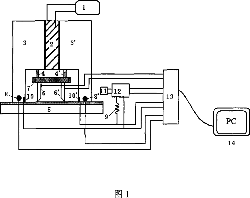
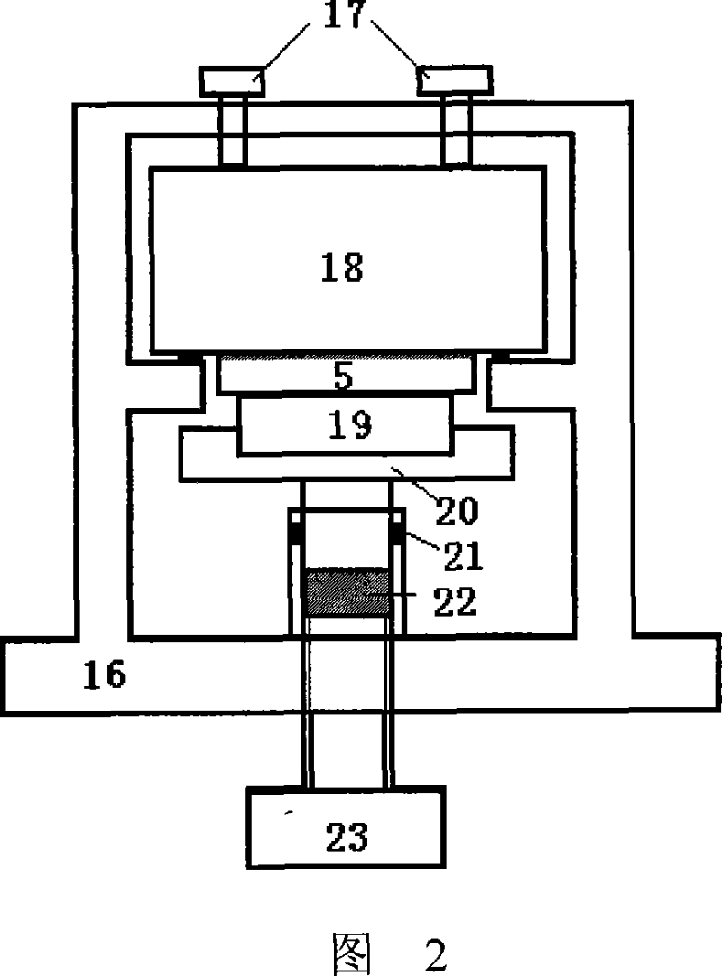
[0014] The structure of the device of the present invention includes three parts: a test component, a test platform, and a data transmission and acquisition device.

[0015] As shown in Figure 1, the structure of the test assembly is as follows: the thermopile 2 is connected to the DC power supply 1; the cold-end heat-conducting copper block 3 and the hot-end heat-conducting copper block 3' are respectively located at the cold end and the hot end of the thermopile 2, and the three are fixed In order to realize good heat conduction between the two ends of the thermopile and the copper block, and then realize the temperature difference between the two ends of the thin film sample 5 . The heat-conducting copper block 3 at the cold end and the heat-conducting copper block 3' at the hot end are preferably symmetrical structures, which form a cavity under the the...


PUM


Abstract

The present invention discloses a device used for measuring seebeck coefficient and electrical resistivity of semiconductor film materials at room temperature, wherein a thermopile and a heat conduction copper block having cold and heat terminals are integrated into a whole block, a cavum is formed at the lower part of the block, and an electric potential probe is deposited in the cavum. The seebeck electric potential detection points and the cold/heat ends thermocouple are deposited at the lower end of the heat conduction copper block; the electric potential probe, the detection points and the thermocouple are connected respectively to a gathering module; a reference resistor is connected in serial to a conversion switch and is also connected to the detection points; a constant current source is connected to the conversion switch; the conversion switch is connected to a data gathering module; the data gathering module is connected to a computer wherein gathered data is processed through a virtual instrument software to obtain the detection results. A detection platform is divided into two parts, wherein the upper part is used for fixing detection modules, and the lower part is used for supporting samples and has a screw used for lifting samples upwards to achieve a contact of samples and detection points. Said device is capable of perform a measurement of seebeck coefficient and electrical resistivity at the same time without destroying the thin film; furthermore, the measuring course is simple, and both the device lost and the testing cost are lower.

Description

technical field [0001] The invention belongs to the technical field of semiconductor testing devices, in particular to a device for measuring the Seebeck coefficient and resistivity of semiconductor thin film materials. Background technique [0002] Seebeck coefficient and resistivity are important thermoelectric transport performance parameters of materials. Accurate determination of them has very important application value and theoretical significance for in-depth study of thermoelectric transport mechanism of semiconductor materials, especially for in-depth research and development of new semiconductor thermoelectric materials and devices. Many devices for testing film resistivity have been developed at present, but there are few test devices for film Seebeck coefficient. Existing test devices related to film Seebeck coefficient and resistivity mainly have the following problems: 1) The determination of the Seebeck coefficient is usually determined by the temperature di...

Claims


Application Information

Patent Timeline
IPC IPC(8): G01N27/18G01N27/04
Inventor 杨君友肖承京朱文鲍思前樊希安段兴凯张亲亲李良彪李凯张同俊
Owner HUAZHONG UNIV OF SCI & TECH
Why Eureka
Try Eureka