Heat activated traveling wave thermoacoustic cooling device with coaxial structure using solar energy

A coaxial structure, traveling wave thermoacoustic technology, applied in solar thermal devices, machines using solar energy, heating devices, etc., can solve the problems of uncompact structure, low thermal efficiency, no solar energy, etc. The effect of reducing the DC loss of the circuit and eliminating the DC

Inactive Publication Date: 2007-09-26
TECHNICAL INST OF PHYSICS & CHEMISTRY - CHINESE ACAD OF SCI
View PDF0 Cites 7 Cited by
  • Summary
  • Abstract
  • Description
  • Claims
  • Application Information

AI Technical Summary

Problems solved by technology

The refrigerator adopts an essentially irreversible standing wave thermoacoustic refrigeration process, and the thermal efficiency is not high
[0005] Since the existing traveling-wave thermoacoustic refrigerators driven by traveling-wave engines are arranged in a circular circuit, the structure

Method used


Image

  • Heat activated traveling wave thermoacoustic cooling device with coaxial structure using solar energy
  • Heat activated traveling wave thermoacoustic cooling device with coaxial structure using solar energy
  • Heat activated traveling wave thermoacoustic cooling device with coaxial structure using solar energy

Examples


Embodiment 1

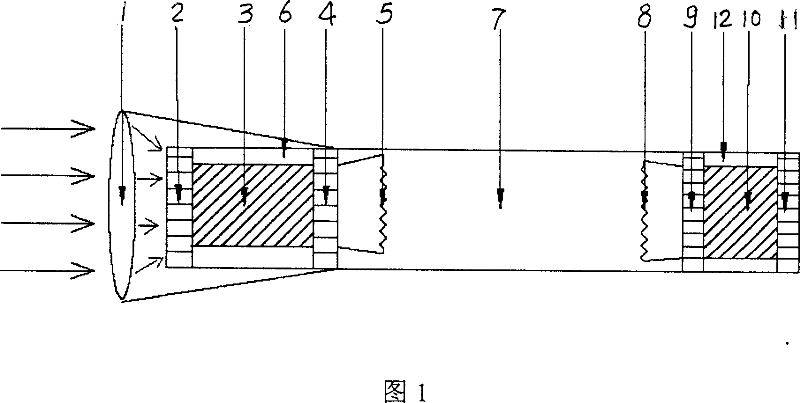
[0043]Embodiment 1: A heat-driven traveling wave thermoacoustic refrigeration device using the coaxial structure shown in FIG. 1 . Where 1 is the cross-sectional area is 1m 2 2 is the hot end heat exchanger of the traveling wave thermoacoustic engine, its surface is coated with 304 stainless steel chemical conversion coating, and the interior is filled with LiNO 3 , 3 is the regenerator filled with 200-mesh wire mesh, 4 is the room temperature end heat exchanger in the form of water cooling, 5 is the first inertial elastic membrane, 6 is the feedback tube, and 7 is the resonance tube, which consists of a Φ80mm long 1m 8 is the second inertial elastic membrane, 9 is the cold end heat exchanger of the traveling wave thermoacoustic refrigerator, 10 is the regenerator filled with 400-mesh wire mesh, and 11 is the room temperature heat exchange in the form of water cooling device, 12 is a feedback tube.

[0044] Both the above-mentioned traveling wave thermoacoustic engine and re...

Embodiment 2

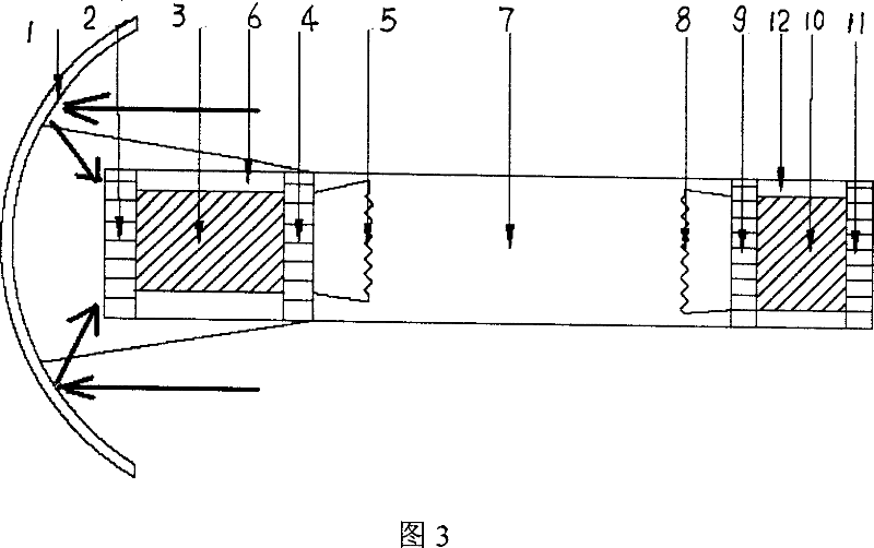
[0045] Embodiment 2: A heat-driven traveling wave thermoacoustic refrigeration device using the coaxial structure shown in FIG. 3 . Where 1 is the cross-sectional area is 1m 2 The concave mirror of , 2 is the hot end heat exchanger of the traveling wave thermoacoustic engine, its surface is coated with Cr 2 o 3 coating, filled with Na 2 0, 3 is the regenerator filled with 200-mesh wire mesh, 4 is the room temperature end heat exchanger in the form of water cooling, 5 is the first inertial elastic membrane, 6 is the feedback tube, and 7 is the resonance tube, which is 0.2m long Φ80mm circular tube and 1.8m long conical tube, 8 is the second inertial elastic membrane, 9 is the cold end heat exchanger of the traveling wave thermoacoustic refrigerator, 10 is the regenerator filled with 400 mesh screen, 11 12 is a feedback pipe for adopting a water-cooled room temperature end heat exchanger.

[0046] The above-mentioned traveling wave thermoacoustic engine and refrigerator both...

Embodiment 3

[0047] Embodiment 3: A heat-driven traveling wave thermoacoustic refrigeration device using the coaxial structure shown in FIG. 1 . Where 1 is the cross-sectional area is 1m 2 The convex lens, 2 is the hot end heat exchanger of the traveling wave thermoacoustic engine, its surface is coated with "cobalt carbide / Co" coating, and the interior is filled with phase change heat storage with the composition of "50%LiOH / 50%LiF" Materials, 3 is the regenerator filled with 200 mesh wire mesh, 4 is the room temperature end heat exchanger in the form of water cooling, 5 is the first inertial elastic membrane, 6 is the feedback tube, 7 is the resonance tube, which consists of a 2m long Φ80mm circular tube, 8 is the second inertial elastic membrane, 9 is the cold end heat exchanger of the traveling wave thermoacoustic refrigerator, 10 is the regenerator filled with 400 mesh screen, 11 is the room temperature end exchanger in the form of water cooling Heater, 12 is feedback tube.

[0048]...


PUM

PropertyMeasurementUnit
The inside diameter ofaaaaaaaaaa

Abstract

It relates to a solar energy coaxial heat drive traveling wave heating and sound cooling device, that comprises the coaxial traveling wave heating and sound cooling engine and traveling heating and sound cooling machine, harmonic tube connected between the traveling wave heating and sound cooling engine, and traveling wave heating and sound cooling machine heat exchanger, light gathering device installed at the front of the thermal end heat exchanger, a first inertia spring film inside the harmonic vibrating tube, and the second inertia spring film inside the harmonic vibrating tube.Using coaxial structure, using the self mass of the spring film to replace the inertia pipe inside the cooling system, it has compact structure, driven by the solar source, coated with optical frequency optional coating, with highly efficient use of solar energy.

Description

[0001] technical field [0002] The invention mainly relates to refrigeration and low-temperature technology, in particular to a heat-driven traveling wave thermoacoustic refrigeration device with a coaxial structure utilizing solar energy. Background technique [0003] The heat-driven traveling wave thermoacoustic refrigeration device is a refrigeration device that uses an inert gas that does not pollute the environment as a working medium and has no moving parts at all. It operates stably and reliably, has a long service life, can utilize low-grade heat sources such as industrial waste heat and solar energy, and can theoretically achieve Carnot efficiency, and has broad development prospects. [0004] In 2000, Adeff and Hofler of the U.S. Naval Postgraduate School designed and manufactured a solar-driven standing wave thermoacoustic refrigerator [1] . They used an 18-inch (0.457m) diameter Fresnel lens to concentrate light, achieve a maximum temperature of 450°C at the hot...

Claims


Application Information

Patent Timeline
IPC IPC(8): F25B9/00F24J2/00G10K15/04
CPCF25B2309/1403F25B2309/1406F25B9/145F25B27/002
Inventor 罗二仓戴巍朱尚龙吴剑峰
Owner TECHNICAL INST OF PHYSICS & CHEMISTRY - CHINESE ACAD OF SCI
Why Eureka
Try Eureka