Constant Loading tension-compression test machine

A testing machine and constant load technology, which is applied in the direction of testing material strength by applying stable tension/compression, and testing material strength by applying stable shear force, which can solve the problems of inability to automatically record data, low device accuracy, and floor space Large and other problems, to achieve the effect of simple structure, large measuring range and low cost

Inactive Publication Date: 2007-09-26
UNIV OF SCI & TECH BEIJING
View PDF0 Cites 53 Cited by
  • Summary
  • Abstract
  • Description
  • Claims
  • Application Information

AI Technical Summary

Problems solved by technology

[0003] The purpose of the present invention is to provide a constant load tensile and compression testing machine, which solves the problems of expensive equipment in the process of use, large floor area or low de

Method used


Image

  • Constant Loading tension-compression test machine

Examples


Embodiment Construction

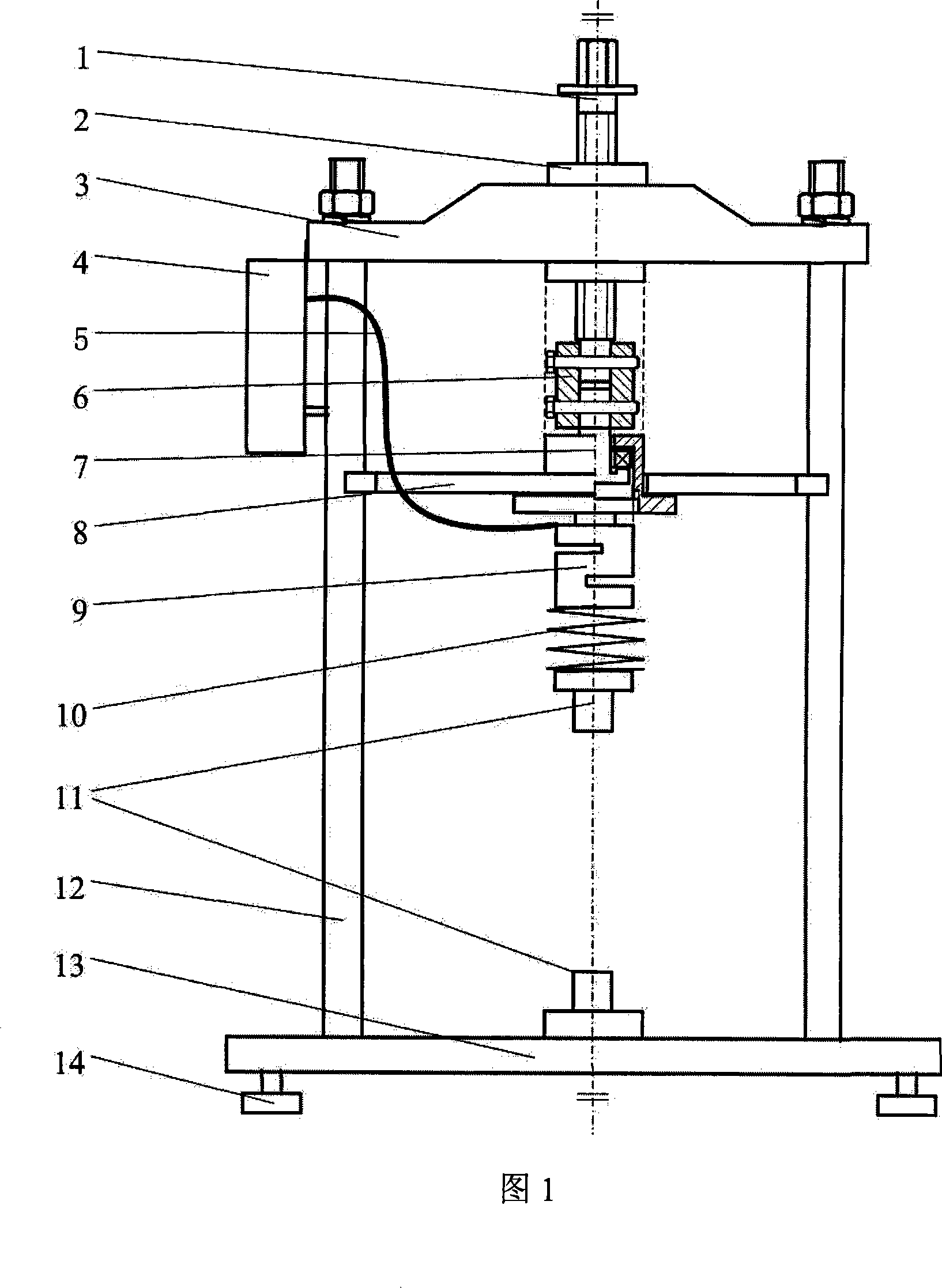
[0011] Fig. 1 is an embodiment of the present invention.

[0012] The frame includes a beam 3 , two columns 12 , a base 13 and four feet 14 . These four components form a strong frame to mount and support the entire installation. The legs are fixed on the four corners below the base 13, and the height can be adjusted by threads to level the base. Two upright posts are installed on the base 13 for supporting the beam 3 and bearing the additional load during work. The crossbeam 3 is installed on the top of the crossbeam, and its two ends are firmly connected with the columns 12 .

[0013] The transmission part is composed of a transmission screw 1, a transmission nut 2, a connector 6, a thrust bearing mechanism 7, and a horizontal limiter 8. In the preferred example, the nut 2 is fixed on the crossbeam 3, the transmission part is connected with the frame through the nut 2, the transmission part is driven up and down by rotating the screw 1, the loading of the equipment is con...


PUM


Abstract

This invention relates to one constant pushing test machine in metal materials stretching test technique field, which comprises machine rack, drive part and force test part, wherein, the rack is composed of socket, stand column, level beam and rack leg; the stand column is fixed onto socket with top end connected to beam to form one frame to fix drive and test parts; the drive part passes level beam fixed onto rack beam through drive screw or drive screw bar; the force test part is fixed on down end of drive part to realize puling and compressing data test.

Description

technical field [0001] The invention belongs to the technical field of tensile testing of metal materials, and in particular provides a constant-load tension-compression testing machine. technical background [0002] The constant load tensile test equipment is the most commonly used equipment for testing the tensile mechanical properties of materials and the corrosion resistance under tensile stress conditions [GB 4157-84 Metal Resistance to Sulfide Stress Corrosion Listed Constant Load Tensile Test Methods] [NACE TM0177-96 in h 2 Laboratory Tests of Resistance to Specific Forms of Environmentally Cracking Metals in S Environments]. At present, this type of equipment is mainly weight-type constant load tensile testing machine (or computer-controlled material tensile testing machine or universal testing machine) and force measuring ring (or spring device). The former test is accurate, but the equipment is expensive and occupies a large area, and it is inconvenient to carry ...

Claims


Application Information

Patent Timeline
IPC IPC(8): G01N3/24G01N3/08
Inventor 刘智勇董超芳李晓刚翟国丽
Owner UNIV OF SCI & TECH BEIJING
Why Eureka
Try Eureka