Synchro motor drive device

A synchronous motor and driving device technology, applied in the control of electromechanical transmission, motor generator control, AC motor control, etc., can solve problems such as difficult starting, control phase error, motor reversal, etc., to avoid torque ripple, The effect of suppressing inversion and simple composition

Active Publication Date: 2007-09-26
HITACHI IND PROD LTD
View PDF0 Cites 17 Cited by
  • Summary
  • Abstract
  • Description
  • Claims
  • Application Information

AI Technical Summary

Problems solved by technology

[0006] However, in the conventional technology, torque ripple occurs due to the superposition of higher harmonics, which may be affected by mechanical resonance, etc., making it difficult to start smoothly
In addition, in the case of using significant polarity, for example, in the case of a synchronous motor with a damper winding, the significant polarity decreases due to the influence of the damper winding, making it difficult to apply the conventional technology
In addition, in the case where voltage detection is required, it is easily affected by voltage detection errors at low speeds
Furthermore, the control phase error caused by the above-mentioned higher harmonics and voltage detection error may sometimes cause the motor to reverse, and when the angle that can be reversed is limited due to mechanical constraints, it will cause problems.
In addition, in the design of the speed control system and the speed estimation system, the constants of the motor and the mechanical system are required, and it is difficult to apply them if they cannot be clearly grasped.

Method used


Image

  • Synchro motor drive device
  • Synchro motor drive device
  • Synchro motor drive device

Examples


Embodiment 1

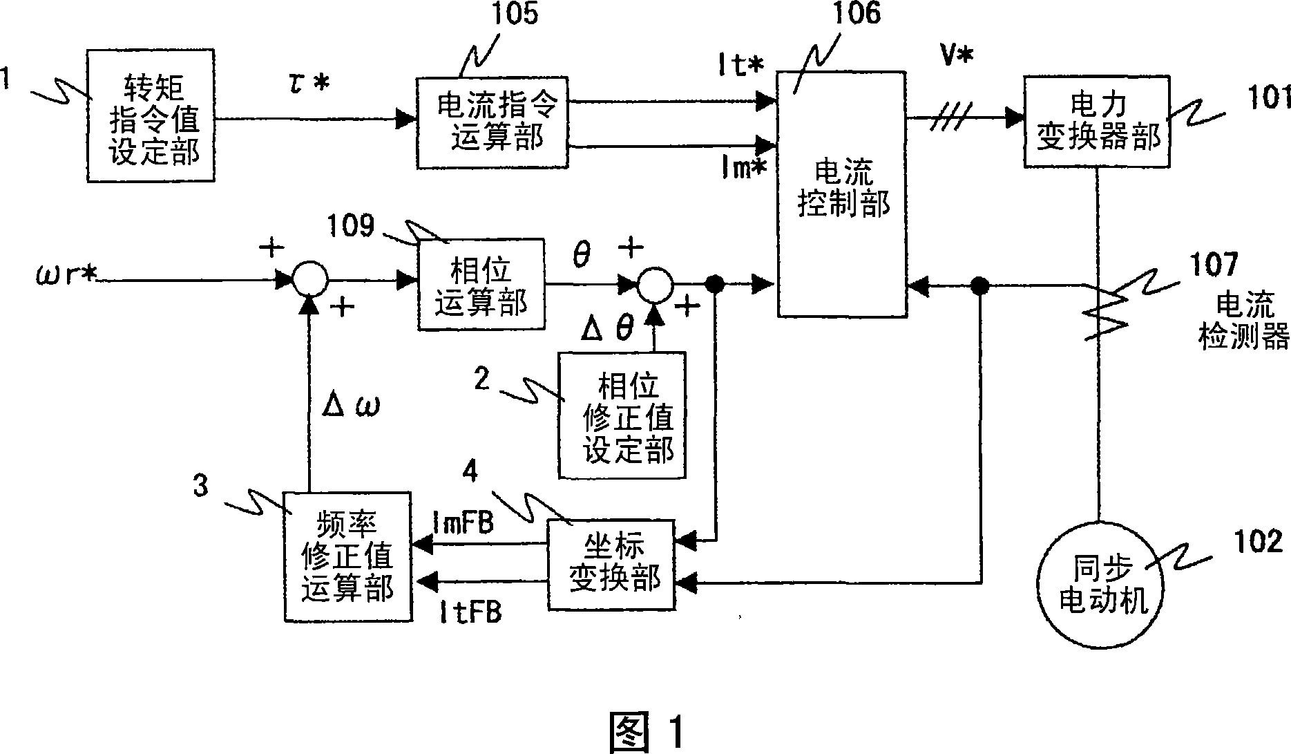
[0024] The differences between the induction motor drive device of this embodiment and the prior art shown in FIG. 10 will be described using FIGS. 1 to 3 . In addition, what is involved here is the control method from starting to accelerating to a given speed. In the torque command value setting section 1, let the torque command value τ * It corresponds to acceleration torque + load torque, and is set to, for example, about 60% of the rated torque. Next, in the current command computing unit 105, the torque current command It is set * = given value, excitation current command Im * =0. Since the magnetic flux is generated by the field current of another field device, it is generally controlled so that Im=0. At this time, the currents Id, Iq, magnetic fluxes Φd, Φq, and generated torque τm of the synchronous motor 102 are as shown in (Formula 2) to (Formula 6), respectively. In addition, the phase difference Δ is the phase deviation between the d-axis and the m-axis shown...

Embodiment 2

[0036] Differences between this example and example 1 will be described. In this embodiment, the phase correction value Δθ is gradually changed by degrees such as 90° or 45°, or 30°, or 10° below 90°. By doing this, the rotation becomes smoother.

Embodiment 3

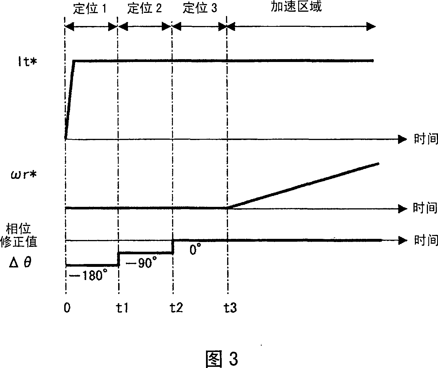
[0038] The differences between this example and example 1 and example 2 will be described using FIG. 4 . In FIG. 4, compared with FIG. 3 of the first embodiment, the time t1 for setting the phase correction value Δθ to the initial setting value is shorter than the time t2-t1 and t3-t2 for changing the phase correction value Δθ thereafter. This is because, in Fig. 11, starting at a position staggered by 180° from the t-axis (current axis) and the d-axis (magnetic pole axis) cannot start, and demagnetization is caused by the t-axis current, so the phase correction When the value Δθ changes and the t-axis (m-axis) moves, it may not start due to demagnetization. In addition, the reason why it can be started within t1 is that it is close to the phase correction value Δ=0, and then when the phase correction value Δθ moves by 90°, it is still within the startable range, as long as the demagnetization of the initial phase correction value Δθ is prevented. Can. In this embodiment, b...


PUM


Abstract

The invention provides a synchronous electromotor driving device which smoothly starts an acceleration synchronous electromotor without speed and a position speed, and restrains reversion. The synchronous electromotor driving device of the invention controls magnitude, frequency, phase of an output voltage, addes a gived phase corrected value to the phase when a synchronous electromotor is started, modifies the phase corrected value more than once, and corrects the frequency or phase based on a detection value of an output current. In addition, when the phase corrected value is modified, the phase is increased at a positive rotation direction of the electromotor, for example, gradually incresed to lower than 90 degrees. Morever, when the gived phase corrected value initially modified, a time setting an initial phase corrected value is shorter than a time setting a modified phase corrected value.

Description

technical field [0001] The present invention relates to a motor drive device for variable-speed operation of a synchronous motor, in particular to a motor drive device for starting and accelerating a synchronous motor without using speed and position sensors. Background technique [0002] In the speed and position sensorless control of synchronous motors, there has been a kind of superimposed high-order harmonics on the output current or output voltage, using the inductance in the magnetic flux axis (d axis) and the axis (q axis) perpendicular to the magnetic flux axis The difference between (Ld, Lq) is used to detect the speed or magnetic pole position. FIG. 10 shows the technology of Patent Document 1 as a conventional technology. In addition, although the synchronous motor in FIG. 10 is a permanent magnet type synchronous motor, the operation is the same if a winding type synchronous motor with a magnetic field device is used. In the speed control unit 103, the speed co...

Claims


Application Information

Patent Timeline
Patent Type & Authority Applications(China)
IPC IPC(8): H02P21/00H02P6/18H02P27/04H02P6/06H02P6/08H02P6/182H02P6/28H02P21/22H02P21/34H02P23/16
Inventor 永田浩一郎奥山俊昭根本治郎片山敏男秋田佳稔
Owner HITACHI IND PROD LTD
Why Eureka
Try Eureka