Self-expanding stent axial wire-drawing tensioning mechanism

A tensioning mechanism, axial technology, used in stents, medical science, prostheses, etc., can solve problems such as obstruction of blood flow, slippage, and difficulty in positioning

Active Publication Date: 2007-10-03
BEIJING BALANCE MEDICAL
View PDF0 Cites 67 Cited by
  • Summary
  • Abstract
  • Description
  • Claims
  • Application Information

AI Technical Summary

Problems solved by technology

The shortcoming of this method is: 1, the sheath tube of the delivery system of existing self-expanding type stent and the stent under radial compression are relatively hard, and flexibility is poor
2. The friction between the self-expanding stent and the sheath of the delivery system is large, which affects the accurate release of the stent; under high compression of the self-expanding stent, the retraction of the sheath will encounter great resistance; and difficulties will also cause the operator to displace the fixed support
3. The thin sheath that is closed laterally prevents the guide wire from passing through the radially compressed stent laterally from inside to outside or from outside to inside. The guide wire obstructs the retraction of the sheath, preventing radial expansion of the self-expanding stent
However, there are still the following disadvantages: 1. The tearable membrane hinders the guide wire from passing through the radially compressed stent laterally from inside to outside or from outside to inside; the only place where the lateral guide wire can pass is the opening of the tearable membrane , but the lateral wire is limited to this only rotation angle
2. After the tearable film fixed on the stent is torn off, the stent expands radially. If the length of the stent becomes shorter after radial expansion, the length of the tearable film remains the same but is greater than the length of the stent after radial expansion. If it is too long Membranes impede blood flow
But there are still the following disadvantages: 1. The stent is only radially compressed at the wire wrapping point. If the stent is long, the overall radial compression of the stent is not enough, or many wrapping wires are required, which makes the structure very complicated; or requires a thin sheath at the same time Further radial compression outside the stent, which makes it lose its open structural advantage
2. If the surrounding wire is only around the outside of the bracket, there is a danger of slipping off from both ends of the bracket; if the surrounding wire shuttles inside and outside the bracket, there is no danger of being slipped off, but the friction with the bracket increases
[0015] 1. Difficulty in positioning: The existing delivery system of the interventional stent valve and the stent valve under radial compression are relatively hard and have poor flexibility. After passing through the aortic arch, they cannot be aligned with the natural aortic valve orifice
The axial upstream and downstream positioning and rotational positioning of the interventional stent valve and its delivery system are not easy due to the instability of the artificial valve under the impact of blood flow
[0016] 2. Position change: Under the high compression of the self-expanding stent valve, the retreat of the traditional sheath will encounter great resistance
[0017] 3. Position adjustment: After the self-expanding stent is fully expanded in the radial direction, if the position is wrong or inappropriate, the position of the self-expanding stent cannot be adjusted.
[0018] 4. Stent recycling: After the self-expanding stent is fully expanded in the radial direction, if the size and size of the stent are wrong, the unsuitable stent cannot be recycled

Method used


Image

  • Self-expanding stent axial wire-drawing tensioning mechanism
  • Self-expanding stent axial wire-drawing tensioning mechanism
  • Self-expanding stent axial wire-drawing tensioning mechanism

Examples


Embodiment Construction

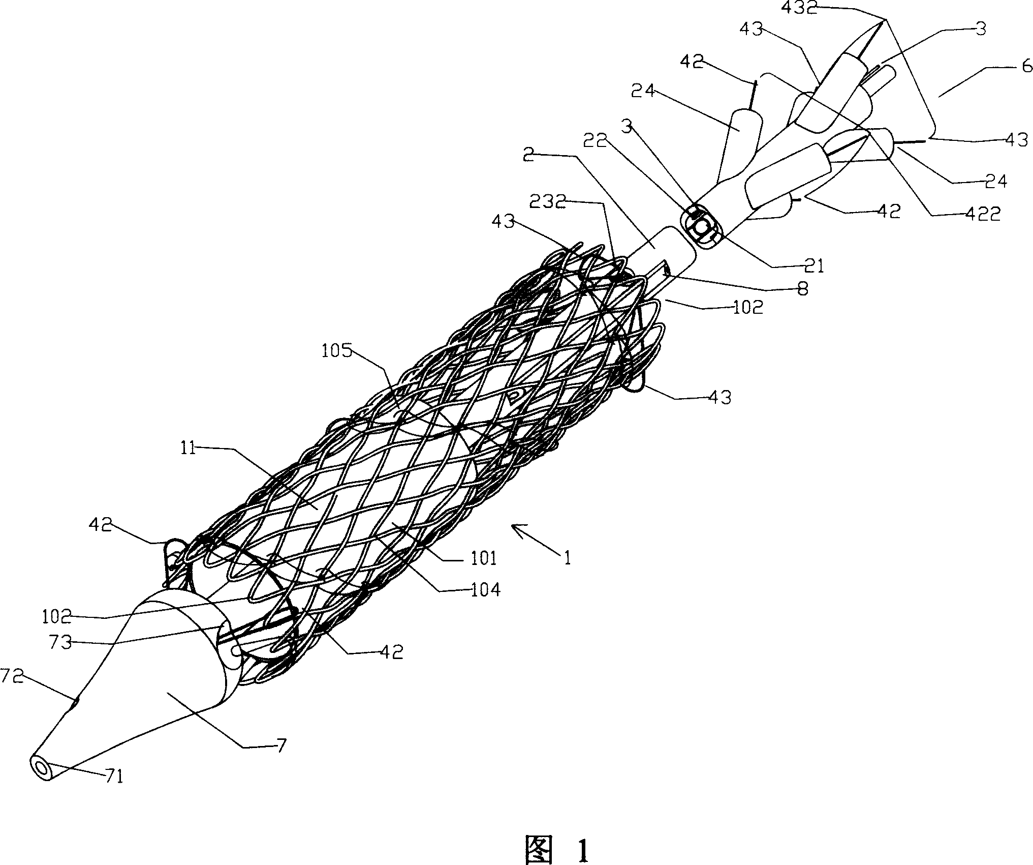
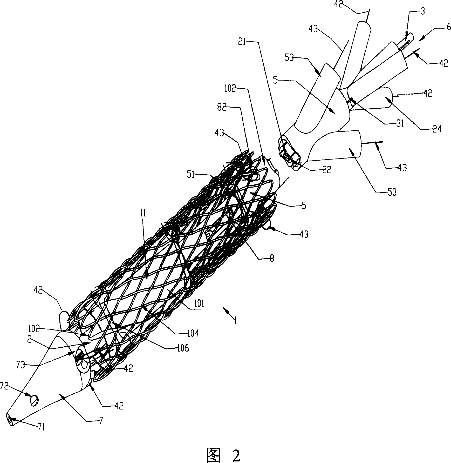
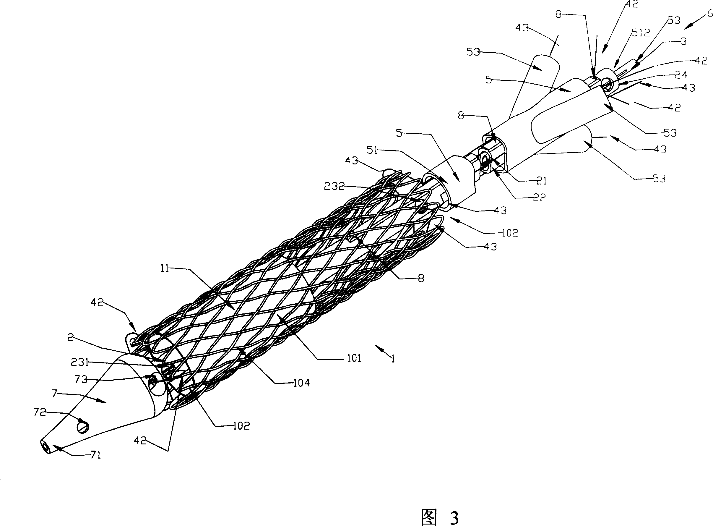
[0049] Referring to Fig. 1 to Fig. 9, the self-expanding stent axial cable tensioning mechanism of the present invention is used to cooperate with the delivery system and various stent pressing mechanisms to tension the self-expanding stent when the self-expanding stent is implanted in the heart vessel. The stent pressing mechanism wherein includes the inventor's flexible connecting ring pressing mechanism and the take-up pressing mechanism (referring to the inventor's other two patent applications: "Self-expanding stent flexible connecting ring pressing mechanism" and "Self-expanding stent flexible connecting ring pressing mechanism" Expansion bracket take-up and pressing mechanism").

[0050] The self-expanding stent 1 involved in the present invention includes a self-expanding stent-graft and a self-expanding stent-valve, and part or all of the stent wall of the self-expanding stent-graft is covered with a membrane 11 . The stent wall of the self-expanding stent valve is pa...


PUM


Abstract

An axially pulled stretch mechanism for a self-expanding stents is composed of an internal tube for the scaffold arranging system, an optional intermediate tube, a locking wire, at least one far-end and at least one near-end pull threads with respective pull rings at their far end, and the open fixers and / or closed thread pinholes at both ends of said scaffold. Its application is also disclosed.

Description

technical field [0001] The invention relates to a tensioning mechanism for various stents implanted in human heart vessels or other luminal organs during delivery, in particular to an axial tensioning mechanism for self-expanding stents. Background technique [0002] The heart is the most important organ of the human body. The heart is divided into two parts, the left and the right, and each part includes the atrium and the ventricle. The left and right atria and right and left ventricles are separated by the atrial and ventricular septum, respectively. There are four heart valves in the heart, namely the tricuspid valve, pulmonary valve, mitral valve and aortic valve. In the human blood circulation mechanism, the four heart valves play a vital role. The hypoxic blood from the systemic circulation mechanism enters the right atrium through the vena cava, and then enters the right ventricle through the tricuspid valve. The contraction of the right ventricle pushes the blood ...

Claims


Application Information

Patent Timeline
Patent Type & Authority Applications(China)
IPC IPC(8): A61F2/84A61B17/00A61F2/90A61F2/95
CPCA61F2/95A61F2002/9511A61F2002/9505A61F2/90
Inventor 温宁
Owner BEIJING BALANCE MEDICAL
Why Eureka
Try Eureka