
Apparatus for cold rolling copper ball

A technology of copper balls and rolls, applied in bearing components, shafts and bearings, mechanical equipment, etc., can solve the problems of long time for adjustment and maintenance, high equipment adjustment requirements, boring guide plate rolling mill, etc. Shorten welding, stable and reliable effect of forming

Active Publication Date: 2007-10-03
广东南方特种铜材有限公司
View PDF0 Cites 7 Cited by
  • Summary
  • Abstract
  • Description
  • Claims
  • Application Information

AI Technical Summary

Problems solved by technology

This device is improved on the basis of the original steel ball hot rolling equipment. During the production of cold rolled copper balls, the original steel ball hot rolling equipment adopts a fixed plate type guide plate structure for the cold rolling transmission of copper balls. The plate guide plate is mainly composed of two flat guide plates whose upper and lower end surfaces are relatively parallel. Rollers are arranged on both sides of the flat guide plate. Touch the surface of the flat guide plate and convey it out along the length direction of the flat guide plate. This kind of fixed guide plate needs to ensure a high degree of parallelism, and the distance between the guide plate and the roll is relatively strict, so the equipment adjustment requirements are high, and the workload is large. And maintenance takes too long (sometimes the time taken is almost close to the normal production running time); at the same time, due to the narrow width of the guide plate (generally 2-6mm), when the copper billet rod is slightly bent or the diameter of the rod changes, There will be scraping on the surface of the copper ball product, or the "stuck" of the guide plate will cause the rolling mill to be boring, which will lead to the waste of the previous complicated adjustment work, and all the adjustment work must be repeated, and the production stability is relatively low. Difference

Method used


Image

  • Apparatus for cold rolling copper ball
  • Apparatus for cold rolling copper ball
  • Apparatus for cold rolling copper ball

Examples


Embodiment 1

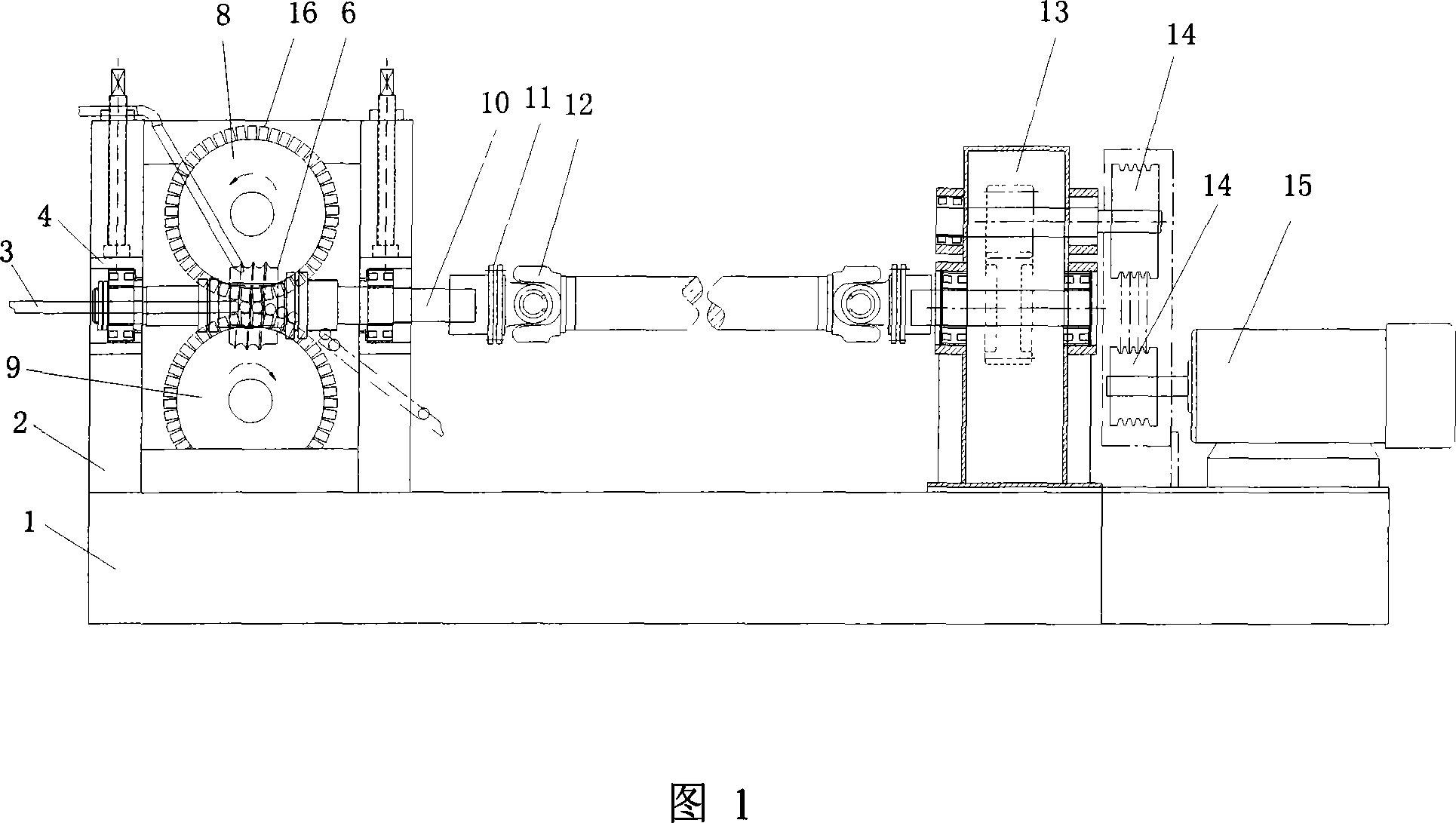
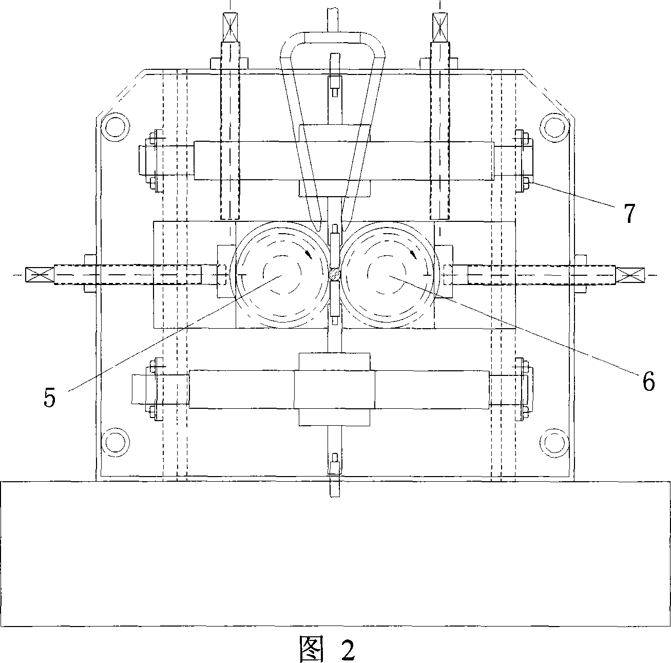
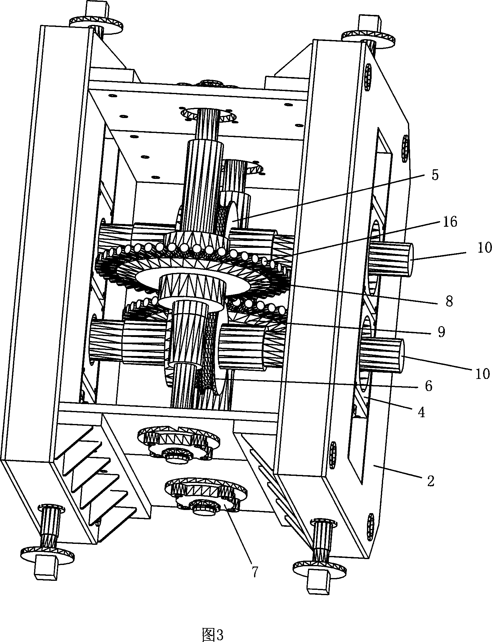
[0028] The copper ball cold rolling mill shown in Figure 1 and Figure 2 includes a fixed frame 1, a copper ball cold rolling device, a power mechanism, and a transmission shaft. The copper ball cold rolling device on the left is connected with the power mechanism on the right through the transmission shaft in the middle, and is installed on the fixed frame 1. The power mechanism on the right side comprises motor 15, belt pulley 14, speed reducer 13. The motor 15 drives the belt pulley 14 to rotate, and through the speed reducer 13, drives the transmission shaft to rotate. The copper ball cold rolling device includes a frame 2, an upper guide plate 8, a lower guide plate 9, a left roll 5, and a right roll 6. The upper guide disc 8 and the lower guide disc 9 are movable circular guide discs, the upper circular guide disc 8 and the lower circular guide disc 9 are rotatably connected on the frame 2, and the upper circular guide disc 8 and the lower circular guide disc 9 are on th...

Embodiment 2

[0035] Fig. 6 has shown another structure of the present invention, as can be seen from Fig. 6, this copper ball cold-rolling device is the same as embodiment 1 except the following features: the lower round guide plate 9 is replaced by the flat guide plate 17 that is arranged horizontally, described The upper circular guide plate 8 is rotatably connected to the frame 2, the flat guide plate 17 is fixed on the frame 2, and the left and right roll screws 5, 6 are embedded in the teeth of the upper circular guide plate 8. 16 and between the upper circular guide plate 8 and the lower flat guide plate 17.


PUM


Abstract

A cold rolling machine for manufacturing copper ball is composed of machine frame, upper toothed guide disc, lower toothed guide disc (or lower guide plate), and left and right rolling rollers with spiral slot engaged with the teeth on guide discs for preventing the static friction between fixed guide plate and copper ball.

Description

technical field [0001] The invention relates to pressure processing equipment for nonferrous metals, in particular to a copper ball cold rolling device. Background technique [0002] Anode copper ball products are a new type of copper-phosphorus alloy material developed in recent years. They are mainly used as anode materials for circuit connection of printed circuit boards and electroplating on the surface of circuit boards. They are one of the basic materials for electronic information manufacturing. The copper ball cold rolling device is a new type of forming cold rolling equipment that has been put into use in China in recent years. This device is improved on the basis of the original steel ball hot rolling equipment. During the production of cold rolled copper balls, the original steel ball hot rolling equipment adopts a fixed plate type guide plate structure for the cold rolling transmission of copper balls. The plate guide plate is mainly comp...

Claims


Application Information

Patent Timeline
Patent Type & Authority Applications(China)
IPC IPC(8): B21H1/14
Inventor 林瑞李力李倬
Owner 广东南方特种铜材有限公司
Learn More